2014 Ford F150 Serpentine Belt Diagram: Proper Routing 2026

The 2014 Ford F150 serpentine belt routes around the crankshaft, alternator, water pump, power steering/idler pulley, and belt tensioner. On the 5.0L V8, rotate the tensioner clockwise using a 3/8-inch drive breaker bar to release tension. The primary drive belt uses Motorcraft JK6-511-A, while the 3.5L EcoBoost requires Motorcraft JK6-515.
📌 Key Takeaways
- 5.0L Coyote engines use a 3/8-inch square drive to rotate the spring-loaded belt tensioner clockwise to slacken the belt.
- 3.5L EcoBoost and 5.0L V8 engines utilize separate stretch belts or dedicated second belts for the A/C compressor.
- Factory tensioner mounting bolt torque is 35 lb-ft (47.5 Nm); always verify proper pulley alignment upon installation.
- Premature wear typically stems from a seized idler pulley bearing or weak automatic tensioner spring damping.
- Replace the belt if you observe more than 3-4 cracks per inch, edge fraying, or rib contamination with engine oil.
Locating the correct 2014 Ford F150 serpentine belt diagram is essential when servicing front-end accessory drive (FEAD) assemblies across the twelfth-generation platform. Ford deployed four distinct powertrain architectures for the 2014 model year: the 3.7L Cyclone V6, the 3.5L EcoBoost twin-turbo V6, the 5.0L Coyote V8, and the heavy-duty 6.2L Boss V8. Depending on engine displacement, your truck utilizes either a single multi-rib drive setup or a dual-belt configuration that separates main accessory operation from the air conditioning circuit. Precise routing around the automatic belt tensioner, idler pulley, water pump, alternator, and crankshaft harmonic balancer prevents premature belt degradation, slip-induced charging failure, and harmonic vibration damage.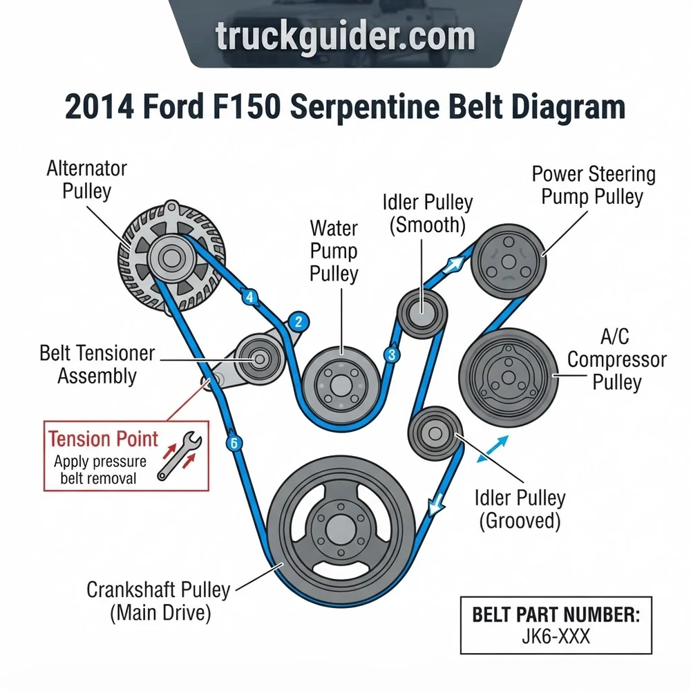
2014 Ford F150 Serpentine Belt Diagram by Engine Option



Each factory powertrain variant requires an exact belt routing path to maintain adequate surface contact arc (wrap angle) over driven pulleys and ensure correct rotational direction for critical components like the reverse-rotation water pump.


Ford 3.7L Cyclone DOHC V6 Pulley Diagram


The 3.7L Duratec/Cyclone V6 uses an Electric Power-Assisted Steering (EPAS) rack, eliminating a conventional hydraulic pump pulley from the front timing cover. The primary FEAD arrangement features a mechanical spring-loaded automatic belt tensioner positioned centrally between the alternator and the engine water pump.
Starting from the top of the grooved crankshaft harmonic balancer, the inner multi-rib face of the main belt travels upward and over the water pump pulley. It descends downward around the grooved alternator pulley located on the lower passenger side. From the alternator, the flat back of the belt loops over the smooth idler pulley situated above the alternator bracket, routes under the smooth contact roller of the automatic belt tensioner, and tracks back to complete the loop around the crankshaft.
The air conditioning circuit runs independently on the lower passenger side. The 3.7L uses a secondary stretch-fit belt that links the outer groove of the harmonic balancer directly to the A/C compressor pulley without an auxiliary tensioner mechanism.
Ford 3.5L EcoBoost Twin-Turbo V6 Belt Routing Path
While sharing internal architectural lineage with the naturally aspirated Cyclone, the forced-induction 3.5L EcoBoost FEAD layout integrates unique bracketry and twin turbocharger plumbing clearances. Similar to the 3.7L, the 3.5L EcoBoost utilizes EPAS, which avoids hydraulic routing.


The primary drive belt routing schematic routes the grooved side from the crankshaft balancer upward to the grooved water pump pulley. Leaving the water pump, the belt traverses across to wrap under the high-output alternator pulley on the lower right flank. The return run directs the smooth side of the belt over an upper stationary idler pulley to stabilize belt flutter under high-torque throttle transitions. It then routes under the spring-actuated automatic belt tensioner pulley before terminating the main cycle at the crankshaft.
A secondary stretch-to-fit elastomeric belt drives the A/C compressor directly off the outer crankshaft balancer pulley ring.
Ford 5.0L Coyote Modular V8 Pulley Diagram
The 5.0L 4-valve Coyote V8 features a dual-belt drive layout. Because the 5.0L platform also utilizes EPAS, no hydraulic steering pump is present. However, its coolant pump and high-amperage alternator demand significant wrap angles to counteract transient slip under rapid engine deceleration.


The primary 6-rib accessory belt starts on the inner grooves of the harmonic balancer. It routes directly over the grooved water pump pulley centrally mounted on the engine block. Exiting the water pump to the passenger side, the grooved face wraps around the alternator pulley. From the bottom of the alternator, the flat back side of the belt contacts the smooth idler pulley, which elevates the run to achieve adequate clearance over the engine timing cover boss, before passing under the spring-loaded belt tensioner pulley and returning to the crankshaft.
The A/C compressor is positioned low on the lower passenger side of the block. On the 2014 Ford F-150 5.0L Coyote, the air conditioning system is driven off the front balancer groove via a dedicated 4-rib stretch belt, devoid of any mechanical tensioner or idler pulley.
Ford 6.2L Boss SOHC V8 Pulley Diagram


The heavy-duty 6.2L Boss V8 differs fundamentally from the other 2014 F-150 engines: it does not use EPAS across standard chassis packages, relying instead on a conventional hydraulic power steering system, nor does it employ a stretch belt for the climate control system. Instead, the 6.2L uses a dual-belt configuration where both the primary accessory drive and secondary A/C drive are governed by dedicated mechanical automatic belt tensioners.
The primary serpentine belt routes from the inner crankshaft balancer over the smooth water pump pulley (utilizing the back of the belt for reverse rotation), down to the grooved power steering pump pulley on the lower driver side, across to the lower passenger-side alternator, upward around an upper idler pulley, under the primary automatic belt tensioner, and back to the crank.


The secondary accessory drive utilizes a dedicated 4-rib serpentine belt routed exclusively between the outer crankshaft balancer hub, a secondary mechanical swing-arm tensioner, and the lower A/C compressor pulley.
2014 Ford F-150 Belt Part Numbers and Size Reference


Replacement of front-end drive belts requires adhering to OEM belt rib profiles and effective pitch lengths. Mismatched belt size specifications induce tracking failure, chirping, and rapid bearing failure inside the idler pulley and alternator bearings. The reference table below lists factory Motorcraft specifications alongside standard aftermarket replacement dimensions.
| Engine Displacement | Drive Application | Motorcraft OEM Part Number | Rib Count | Effective Length |
|---|---|---|---|---|
| 3.7L V6 Cyclone | Main Accessory Drive | JK6-508-A (BR3Z-8620-S) | 6-Rib | 50.8 in (1290 mm) |
| 3.7L V6 Cyclone | A/C Compressor (Stretch) | JK4-377 (BR3Z-8620-D) | 4-Rib | 37.7 in (958 mm) |
| 3.5L V6 EcoBoost | Main Accessory Drive | JK6-508-C (BL3Z-8620-A) | 6-Rib | 50.8 in (1290 mm) |
| 3.5L V6 EcoBoost | A/C Compressor (Stretch) | JK4-377-A (BL3Z-8620-B) | 4-Rib | 37.7 in (958 mm) |
| 5.0L V8 Coyote | Main Accessory Drive | JK6-513 (BR3Z-8620-R) | 6-Rib | 51.3 in (1303 mm) |
| 5.0L V8 Coyote | A/C Compressor (Stretch) | JK4-356 (BR3Z-8620-W) | 4-Rib | 35.6 in (904 mm) |
| 6.2L V8 Boss | Main Accessory Drive | JK6-826 (AL3Z-8620-A) | 6-Rib | 82.6 in (2098 mm) |
| 6.2L V8 Boss | A/C Compressor Drive | JK4-406 (AL3Z-8620-B) | 4-Rib | 40.6 in (1031 mm) |
Factory replacement intervals mandate visual inspection of Ethylene Propylene Diene Monomer (EPDM) belts every 15,000 miles, with complete replacement recommended at 100,000 miles or 6 years. EPDM belts do not display traditional cracking; rib wear must be checked with an OEM depth gauge tool.
Step-by-Step 2014 Ford F150 Serpentine Belt Routing Path Guide

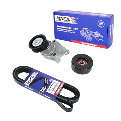


Replacing drive belts on the 2014 F-150 platform requires specific service protocols depending on whether you are servicing the main accessory run or the forward-mounted secondary air conditioning stretch belt. Always complete replacement procedures with the vehicle safely isolated.
Disconnect the negative battery cable with an 8mm wrench prior to servicing the FEAD system. Accidental starter engagement or radiator cooling fan cycling can cause severe crush or pinch injuries around the crankshaft and accessory pulleys.
- Isolate Electrical System and Clear Clearance Paths: Disconnect the negative battery terminal. Loosen the clamps securing the intake air duct to the throttle body and mass airflow (MAF) housing using a flathead screwdriver or 7mm socket. Unclip the airbox upper lid, remove the PCV and breather tubes, and lift the assembly out of the bay to access the front engine accessories.
- Remove the Outer A/C Stretch Belt (3.5L, 3.7L, and 5.0L Engines): Because the air conditioning stretch belt sits on the outer track of the crankshaft harmonic balancer, it blocks removal of the main accessory belt. If the secondary belt is to be reused, install a stretch belt removal tool onto the balancer rim, position a breaker bar and 24mm or 27mm socket (depending on engine variant) onto the harmonic balancer center bolt, and rotate the crankshaft clockwise to walk the belt forward out of the grooves. If replacing with a new component, sever the old stretch belt using heavy-duty shears.
- Relieve Tension on the Primary Drive Belt: Identify the 3/8-inch square drive slot or the integrated cast hex lug on the swing-arm of the automatic belt tensioner. Insert a dedicated serpentine belt tensioner tool or long-handled breaker bar. According to OEM specifications, rotate the tensioner assembly against internal spring pressure (counter-clockwise on 5.0L Coyote and 3.5L EcoBoost engines) until the tensioner reaches its internal stop pin.
- De-thread and Extract the Primary Belt: While maintaining mechanical leverage on the tensioner tool, slip the slackened belt off the smooth water pump pulley or upper idler pulley first. Slowly release the tensioner arm until it rests completely against its unladen stop. Unthread the belt from around the alternator, tensioner roller, and the inner grooves of the harmonic balancer, then extract it upward through the cooling fan shroud void.
- Inspect and Spin-Test Driven Components: Before installing new components, manually rotate the water pump, idler pulley bearings, tensioner roller, and alternator clutch pulley. Ensure each rotates freely without radial wobble, binding, axial runout, or grinding noise. Clean all pulley valleys using a nylon bristle brush to remove residual rubber deposits.
- Route the Primary Serpentine Replacement Belt: Feed the new 6-rib OEM belt down into the lower timing cover area. Loop the grooved ribs accurately into the inner track of the crankshaft harmonic balancer. Trace the layout specific to your engine: thread over the alternator, wrap underneath the idler pulley, and direct the smooth reverse-face over the automatic tensioner pulley. Keep the final loop positioned adjacent to the smooth water pump pulley.
- Load the Tensioner and Secure the Primary Run: Re-engage the serpentine belt tensioner tool into the swing arm socket. Rotate the arm to retract the tensioner fully. Slip the final belt loop over the water pump pulley. Double-check that all ribs align centered in every pulley groove before slowly releasing tensioner pressure onto the belt.
- Install the New A/C Compressor Stretch Belt: Position the new 4-rib stretch belt into the grooved clutch pulley of the A/C compressor. Position the lower run onto the bottom grooves of the outer crankshaft harmonic balancer. Mount the wedge-shaped stretch belt installation tool onto the outer crank lip at the 12 o’clock position, pinning the belt behind the tool’s guide ramp. Slowly rotate the harmonic balancer clockwise using your socket and breaker bar. The tool guides the elastic belt over the balancer outer rim until it snaps fully into the tracks. Rotate the crank two full revolutions to verify rib seated alignment.
Automatic Belt Tensioner Adjustment and Inspection Notes


The 2014 Ford F-150 utilizes self-contained mechanical automatic belt tensioners incorporating internal dampening mechanisms and torsional coil springs. These assemblies require no manual clearance calibration, screw-tension tracking, or tension adjustments during service intervals. Instead, belt tension is dynamic, accommodating structural stretch and thermal expansion over the operating envelope of the engine.
To verify dynamic tensioner integrity, observe the arm during idle. Radial movement should not exceed 1/32-inch (0.8 mm) under electrical load. Rapid cyclic fluttering indicates that the internal hydraulic dampener or damping pad assembly has deteriorated, necessitating full tensioner replacement.
Proper tension verification relies on the cast alignment marks located on the stationary tensioner base and the pivoting swing-arm:
- Operating Range Limits: Each OEM tensioner cast housing contains three alignment notches—minimum extension, normal operating band, and maximum travel limit. With a new belt installed and fully seated across all accessories, the indicator mark on the moving arm must reside within the defined operating range notch.
- Under-Tension Diagnostic: If the alignment mark extends past the maximum extension stop, the belt has stretched excessively, or an incorrect effective pitch length has been installed, risking slip against the alternator pulley.
- Over-Tension Diagnostic: If the mark fails to enter the dynamic range and sits tight against the uninstalled limit stop, the belt length is undersized, placing catastrophic side-load pressures onto the water pump and A/C compressor pulley internal bearings.
Inspect the tensioner pulley surface for signs of uneven tracking. Grooved tensioners must not exhibit worn ridge apexes, while flat contact rollers must remain perfectly cylindrical without cupping or conical wear patterns across the face.
Diagnosing 2014 Ford F150 Pulley Alignment and Routing Errors
Accurate pulley alignment and correct belt tracking are critical across modern multi-rib drivetrains. Below are the primary diagnostic indicators, symptoms, and root causes of improper FEAD assembly installation on 2014 F-150 trucks:
- Single-Rib Misalignment / Pulley Offset: The most common installation error occurs when the belt is offset by one rib groove on the crankshaft harmonic balancer or the alternator. Operating the engine with a misaligned rib strips the outside ridge, generates rubber dust along the front timing cover, and causes localized thermal fracturing within 50 miles.
- High-Pitched Cold Start Chirp: Chirping that subsides after engine warmup indicates angular pulley misalignment between the idler pulley and the accessory drives, or structural pulley runout exceeding the OEM limit of 0.030 inches (0.76 mm). Use a straightedge or laser alignment tool to check plane alignment across all driven components.
- Reverse Routing around the Water Pump: On the 3.5L EcoBoost and 5.0L Coyote, routing errors can mistakenly position the grooved side of the belt against smooth idlers or incorrect sides of the water pump. This runs the water pump backward, causing rapid engine overheating under load while the charging and climate systems appear to function normally.
- Stretch Belt Cord Separation: Utilizing pry bars, screwdrivers, or flat chisels instead of an OEM-style stretch belt installation tool overstresses the internal polyamide tensile cords inside the elastomeric A/C belt. This yields localized belt elongation, tracking divergence, and eventual belt snapping under load.
- Belt Squeal Under Rapid Acceleration: If the belt squeals during sharp throttle application, check the internal dampener of the automatic belt tensioner. Loss of torsional resistance reduces belt wrap tension, triggering slip across the small-diameter alternator pulley.
2014 Ford F150 Serpentine Belt Diagram Questions Answered
Can I install the A/C belt on a 2014 Ford F-150 without the special stretch belt tool?
Installing an elastomeric stretch belt without a purpose-built installation guide tool is not recommended by OEM engineering guidelines. Attempting to lever the belt onto the harmonic balancer rim with screwdrivers or pry bars damages the outer pulley track lip and shears the internal tensile cords of the belt. This results in cord unraveling, rib deformation, and premature belt snapping within normal service cycles.
Why does my 2014 F-150 5.0L serpentine belt chirp only when the climate control engages?
A chirp triggered specifically when the A/C engages points to slippage or mechanical failure along the secondary 4-rib drive track, rather than the primary accessory belt. Common causes include oil contamination on the balancer face, excessive wear on the A/C compressor clutch bearing, an internally degrading compressor, or a weakened stretch belt that has lost its elastomeric retention properties.
Does the 2014 Ford F-150 3.5L EcoBoost use a power steering pump pulley?
No, the 2014 Ford F-150 3.5L EcoBoost does not feature a power steering pump pulley. Starting in the 2011 model year, Ford equipped half-ton F-150 configurations with an Electric Power-Assisted Steering (EPAS) rack mounted directly to the subframe. The only engine in the 2014 F-150 lineup that retains a mechanical hydraulic power steering pump is the heavy-duty 6.2L Boss V8.
What is the difference between EPDM serpentine belts and older neoprene belts?


Original equipment 2014 F-150 belts are constructed from Ethylene Propylene Diene Monomer (EPDM) synthetic rubber. Unlike older chloroprene/neoprene belts that cracked when structurally degraded, EPDM compounds gradually lose material along the pulley contact walls via abrasive wear, similar to tire tread. Belt life cannot be assessed by visual inspection alone; you must measure groove depth using an EPDM wear gauge to determine if the belt has worn past serviceable limits.