2014 Chevy Silverado AC System Diagram: Troubleshooting 2026

The 2014 Chevy Silverado AC system operates on R-134a refrigerant. The compressor is driven by the serpentine belt; refrigerant flows from the compressor to the front-mounted condenser, through the orifice tube to the evaporator, and back. Check the blower motor relay in the under-hood fuse block (Fuse 40, 40A) for power issues.
📌 Key Takeaways
- The R-134a system capacity is typically 1.6 lbs (26 oz) for single-zone climate control setups.
- The orifice tube is located in the liquid line near the evaporator inlet and is a common point for debris clogging.
- Always evacuate refrigerant using certified recovery equipment; do not vent to the atmosphere, as it violates EPA regulations.
- The blower motor resistor is a frequent failure point causing fan speeds to lock in high or fail entirely.
- Professional service is required if the compressor clutch fails internally or the system shows signs of metal debris contamination.
Maintaining the climate control performance of your truck requires a deep understanding of the 2014 Chevy Silverado AC system diagram. As a complex network of high-pressure refrigerant lines, electrical control modules, and air distribution ductwork, the HVAC system in the K2XX platform is susceptible to specific mechanical wear. Whether you are addressing a refrigerant leak at the condenser or a malfunctioning blend door actuator within the air handler, referencing the correct schematic is the primary step in professional-grade diagnostics. This guide provides the technical breakdown required to isolate faults, verify sensor inputs, and perform component-level repairs on your Silverado’s cabin cooling architecture.
2014 Chevy Silverado AC System Diagram: Core Components Explained
Recommended Best Deal Products



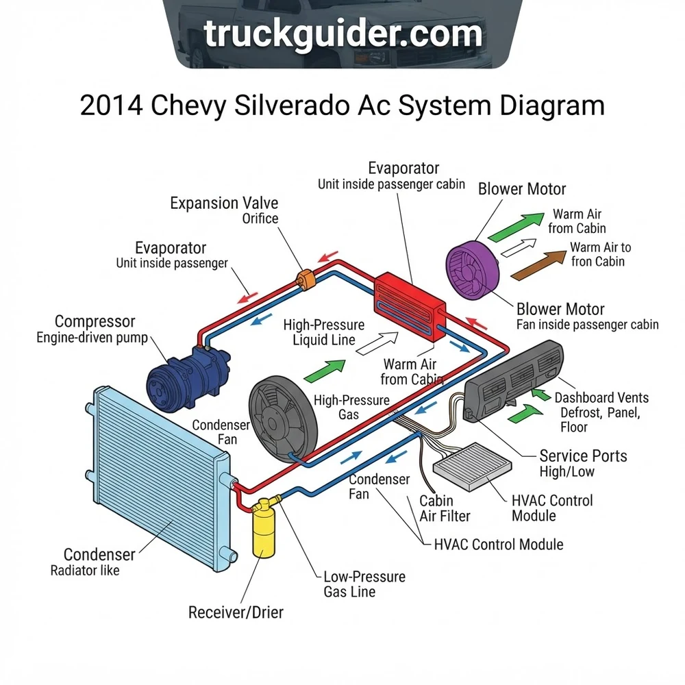
The 2014 Silverado utilizes a belt-driven, variable-displacement compressor system designed to maintain cabin temperatures while optimizing fuel efficiency. Understanding how the refrigerant flows through the loop—and how the air flows through the HVAC module—is critical for accurate troubleshooting.
- AC Compressor: Located on the front engine accessory drive, this unit compresses low-pressure refrigerant vapor into high-pressure, high-temperature gas. In 2014 models, the compressor features an electronic control valve that modulates capacity based on signals from the Engine Control Module (ECM) and the HVAC control head.
- Condenser: Positioned in front of the radiator, the condenser acts as a primary heat exchanger. It dissipates thermal energy absorbed from the cabin into the ambient air, effectively condensing high-pressure gas back into a liquid state.
- Expansion Valve (TXV): The Thermal Expansion Valve regulates the flow of high-pressure liquid refrigerant into the evaporator core. By creating a pressure drop, the valve allows the refrigerant to “flash” into a cold, low-pressure state, enabling the heat absorption process.
- Evaporator Core: Situated inside the air handler housing, the evaporator acts as the cold-side heat exchanger. As the blower motor pushes cabin air across these freezing fins, moisture condenses and heat is removed, resulting in the chilled air output seen at the vents.
- Blower Motor: This high-speed DC motor forces air through the return duct, across the cabin air filter, and through the evaporator and heater core matrix. Monitoring the voltage at the blower motor resistor or controller is often necessary when air flow volume is inconsistent.
On the 2014 Silverado, ensure you inspect the cabin air filter housing if you detect restricted airflow; a clogged filter effectively chokes the entire air distribution system before it reaches the evaporator core.
How to Read the 2014 Chevy Silverado AC System Diagram

Interpreting the technical schematics for your truck is not about intuition; it is about following the logic of the refrigeration loop and the electrical circuit. When you look at the factory diagrams, focus on the connectivity between the HVAC Control Module (HVACCM) and the engine management system.
- Identify High and Low Side Access: Locate the service ports on your 2014 Chevy Silverado AC system diagram. The high-side port (closer to the condenser) and low-side port (closer to the compressor suction line) are your primary diagnostic points for reading refrigerant pressures using a manifold gauge set.
- Trace the HVAC Control Module Signals: Use the diagram to identify the communication path via the GMLAN serial data bus. If the HVAC control head is failing to signal the compressor to engage, the issue often resides in the module-to-ECM communication loop, not the compressor itself.
- Check Schrader Valve Integrity: If your manifold gauges read zero, use the diagram to isolate the physical lines. Check for leaks at the Schrader valves before assuming a compressor failure. A failed valve core is a common, inexpensive culprit that mimics a total system failure.
- Voltage Testing at the Compressor Clutch: Use a multimeter to verify voltage at the clutch connector. If the diagram shows 12V is present but the clutch does not engage, the magnetic coil is likely burnt out or the air gap between the pulley and the armature plate has exceeded the factory specification of 0.020–0.030 inches.
- Validate Grounding Paths: Electrical gremlins often stem from corroded ground studs. Verify the grounding points indicated in the diagram for the blower motor and the HVAC control module. In the 2014 model, grounding strap integrity is vital for preventing erratic behavior in the digital climate controls.
Common 2014 Chevy Silverado AC System Diagram Problems and Fixes
Recommended Best Deal Products


Diagnostic logic for the Silverado platform often centers on mechanical failure of the air distribution components rather than the refrigerant circuit. When the system is charged but output temperatures vary, the problem usually resides in the air handler interior.
Blend Door Actuator Failure: One of the most recurring issues involves the blend door actuator failing to correctly position the air door. When this happens, you may experience hot air on the driver side and cold on the passenger side, or vice versa. By following the diagram, you can identify the specific actuator assembly (Mode, Blend, or Recirculation) and gain access to it by removing the passenger-side dashboard lower trim panel.
Blower Motor Resistor/Controller Issues: If your blower motor only runs on high, or does not run at all, the electronic blower motor controller is the primary suspect. Unlike older trucks that used a simple resistor block, the 2014 Silverado uses a pulse-width modulation (PWM) controller. You must test for the PWM signal coming from the HVACCM to confirm the controller has failed.
Always discharge and recover refrigerant using professional-grade equipment before opening the closed-loop system. Attempting to service a pressurized R-134a system without a recovery machine is a violation of environmental regulations and creates a severe safety hazard.
Refrigerant Pressure Switch Diagnostics: The low-pressure cutout switch is a common point of failure. If the system is fully charged but the compressor refuses to engage, bypass the switch momentarily—not permanently—to see if the clutch engages. If it does, your refrigerant level is low, or the switch itself has an internal open circuit.
Technical Specifications for the 2014 Silverado HVAC System
Refer to the following table for critical system capacities and electrical standards necessary for professional repair work.
| Specification Category | Requirement / Capacity | Notes |
|---|---|---|
| Refrigerant Type | R-134a | Do not substitute |
| Refrigerant Capacity | 1.8 – 2.0 lbs | Varies by engine |
| Compressor Oil | PAG 46 | Essential for lubrication |
| System Voltage | 12.6V – 14.8V | Operational range |
2014 Chevy Silverado AC System Diagram Questions Answered
Where is the orifice tube or TXV located in the 2014 Silverado?
In the 2014 Silverado, the system uses a Thermal Expansion Valve (TXV) rather than a traditional orifice tube. It is located at the firewall, where the hard lines transition into the evaporator core. Accessing it requires removing the lines connected to the block fitting at the rear of the engine bay.
How can I verify the blend door actuator is the cause of the temperature variance?
Use a scan tool capable of reading HVAC body control module (BCM) data. You can command the actuator to move through its full range of motion. If the scan tool shows the signal is sent but the actuator position value does not change, the internal gears of the actuator are stripped.
Is it necessary to remove the dashboard to replace the evaporator core?
Yes, the evaporator core is housed within the main HVAC air handler unit. To remove the housing, the dashboard assembly must be partially or fully removed to provide the necessary clearance for the case to be extracted from the cabin.
Why does my AC compressor cycle on and off rapidly?
This is typically caused by a low refrigerant charge, which trips the low-pressure switch. As the compressor engages, the suction pressure drops below the threshold, triggering the switch to cut power. Once the pressure stabilizes, the cycle repeats. Check for leaks in the condenser or high-pressure hose assemblies immediately.
Always replace the O-rings at any connection point you disassemble. Use PAG oil to lubricate the new O-rings to ensure a proper seal and prevent immediate loss of system pressure upon recharge.
Step-by-Step Guide to Understanding the 2014 Chevy Silverado Ac System Diagram
Identify – Review the diagram to distinguish between the high-side and low-side lines.
Locate – Find the blower motor beneath the passenger-side dashboard and the compressor on the front engine accessory drive.
Reference – Use the electrical pinout in the diagram to verify continuity from the AC relay to the compressor clutch.
Connect/Route – Secure refrigerant lines ensuring proper routing away from hot exhaust manifolds to prevent melting.
Verify – Apply vacuum to the system for 30 minutes to confirm a seal before adding new R-134a refrigerant.
Troubleshoot – Test the blower motor operation via the climate control head if the system remains unresponsive after proper charging.