2014 Ram 5.7 VVT Solenoid Location Step-by-Step Fix 2026

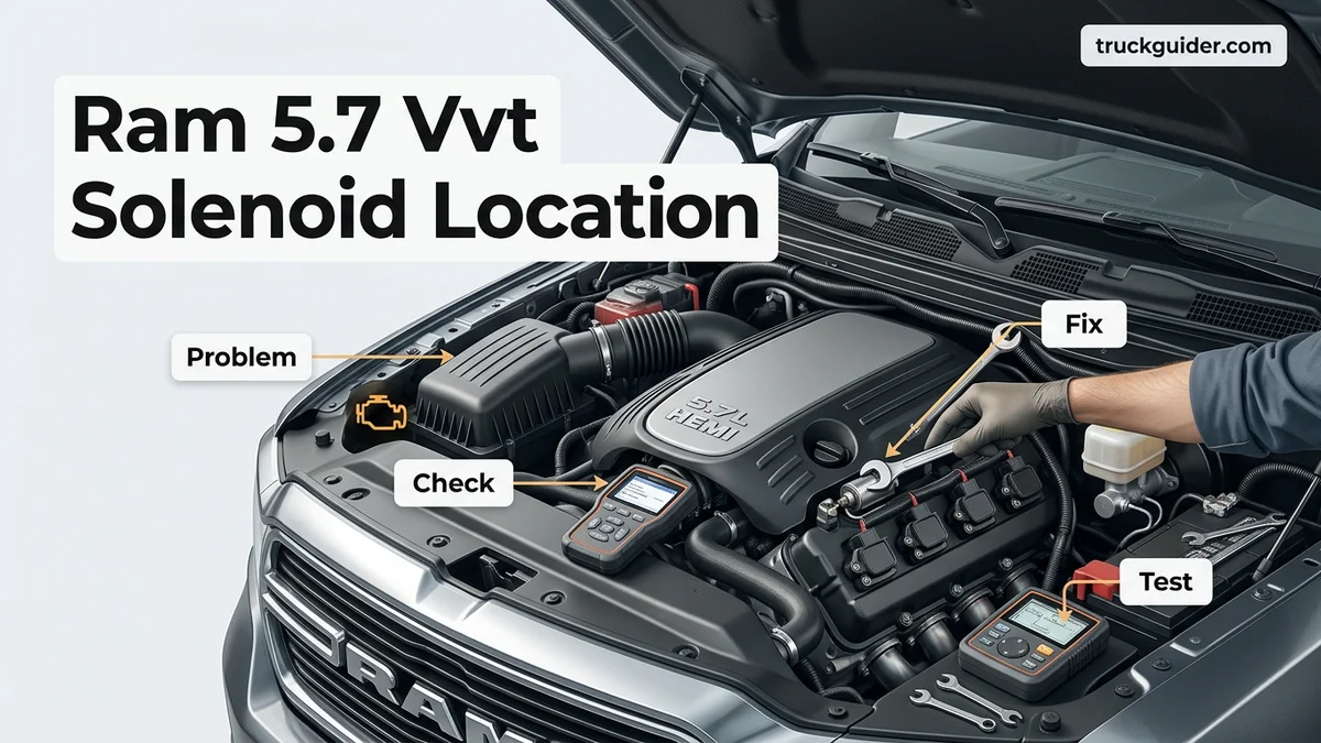
The 2014 Ram 5.7 VVT solenoid is located at the front of the engine block, seated directly behind the timing chain cover and water pump assembly just above the camshaft. Accessing the electrical harness requires top-down removal, while replacing the solenoid valve requires pulling the harmonic balancer and timing cover. Common failure symptoms trigger trouble codes P0011 or P0016 alongside engine sluggishness.
The Variable Valve Timing (VVT) solenoid on your 2014 Ram 1500 5.7L Hemi is bolted directly into the front of the engine block, hidden entirely behind the cast-aluminum timing chain cover and water pump assembly. It mounts right above the camshaft sprocket at the 12 o’clock position. Unlike external sensors that unbolt in minutes, this internal actuator cannot be seen or serviced from the outside of the engine.
Knowing this exact location saves you hours of frustrating diagnostic work. Many truck owners mistakenly tear off the intake manifold or remove valve covers searching for it, confusing the VVT control valve with MDS solenoids or cam sensors. Because accessing this solenoid requires tearing down the front drive assembly, you want absolute certainty about its physical placement and symptoms before turning a single wrench in your garage in 2026.
Key Takeaways
- The VVT solenoid sits inside the front engine block behind the water pump and timing chain cover.
- Electrical connector access differs significantly from full solenoid replacement, which requires removing the harmonic balancer and timing cover.
- Do not confuse the single VVT control solenoid with the four MDS cylinder deactivation solenoids beneath the intake.
- Common fault codes like P000B, P0011, and P0016 signal solenoid sticking, timing deviation, or low oil pressure.
- Always replace the timing cover gasket, front crankshaft seal, and verify clean oil during solenoid replacement.
2014 Ram 5.7 VVT Solenoid Location and Diagnostic Code Symptoms
Recommended Best Deal Products


Your 5.7L Hemi uses an internal oil-control VVT solenoid to direct pressurized engine oil into the camshaft phaser. The unit mounts horizontally into a dedicated bore machined into the front face of the engine block. The electrical harness plugs into the front timing cover, running through a sealed pass-through connector directly to the solenoid body inside.

Exact Front-Engine Mounting Coordinates
To visualize the solenoid before dismantling your truck, look at the center-front of the engine block:
- Behind the Water Pump: The main body of the water pump sits directly over the upper timing cover pocket where the solenoid resides.
- Above the Camshaft Centerline: The solenoid installs just above the timing chain tensioner and cam gear assembly.
- Recessed Engine Bore: It slides into a machined oil gallery channel in the block, secured by a single Torx or 8mm retaining bolt.
- Pass-Through Wiring: The solenoid harness does not run through the top of the intake; its wiring leads straight through a sealed grommet on the timing cover face.
Diagnostic Trouble Codes and Drivability Signs
A failing VVT solenoid prevents the camshaft from advancing or retarding as the powertrain control module commands. Because oil pressure operates the system, mechanical failure or electrical resistance issues produce immediate engine behavior changes.
- DTC P000B: Exhaust Camshaft Position Slow Response (Bank 1).
- DTC P0011: Camshaft Position Timing Over-Advanced.
- DTC P0016: Crankshaft/Camshaft Timing Alignment Correlation fault.
- Severe Low-End Sluggishness: The 5.7L Hemi feels underpowered under 3,000 RPM because the cam remains locked in high-RPM phasing.
- Rough Idle and Engine Shaking: The engine stumbles at stoplights due to improper valve overlap.
- Audible Top-End Rattle: Oil starvation through a clogged solenoid causes the cam phaser to chatter upon cold startup.
From Start to Finish: Finding and Servicing the 2014 Ram 5.7 VVT Solenoid Explained
The Variable Valve Timing (VVT) solenoid on the 2014 Ram 1500 equipped with the 5.7L Hemi V8 plays a crucial role in optimizing camshaft angle, fuel economy, and power delivery. When this electro-hydraulic actuator clogs or fails, it triggers diagnostic trouble codes such as P000B, P0014, or P0016, accompanied by rough idling, sluggish acceleration, and engine pinging. Many owners struggle to locate it because it is not exposed on the exterior of the engine block or cylinder heads. This walkthrough guides you through accessing the hidden lifter valley, pinpointing the solenoid, and servicing it safely and effectively.
Step 1: Relieve Fuel Pressure and Disconnect the Battery
What you need: 10mm wrench or socket, fuel pump fuse removal tool, safety glasses, and clean shop rags.
Instructions: Park the truck on a level surface, set the parking brake, and allow the engine to cool completely. Pop the hood and open the Power Distribution Center (fuse box) located on the driver side. Locate the fuel pump relay/fuse (typically fuse F26 in 2014 models), pull it out, and crank the engine for 5 seconds to purge residual rail pressure. Once the engine stumbles and stalls, switch off the ignition. Use a 10mm wrench to disconnect the negative battery terminal and isolate the cable away from the post to avoid accidental electrical grounding while working around the engine harness.
Pro Tip: Place a rag over the disconnected battery post or wrap the terminal end in a rubber glove to ensure it does not spring back into contact with the post during maintenance.
Step 2: Remove the Air Cleaner Assembly and Throttle Body Duct
What you need: Flathead screwdriver or 8mm nut driver, 10mm socket, and a clean microfiber towel.
Instructions: Unplug the intake air temperature (IAT) sensor connector by sliding back the red locking tab and squeezing the clip. Loosen the worm-gear hose clamps securing the intake ducting to the throttle body and the air filter housing. Unhook the crankcase breather tube running from the oil fill neck into the intake tube. Lift the entire intake resonator box and inlet tube out of the engine bay. Inspect the throttle body entrance for heavy carbon buildup, and cover the open throttle mouth with a microfiber towel to prevent dirt, dropped hardware, or stray debris from entering the intake plenum.
Pro Tip: Take extra care when prying Chrysler‘s red harness locking clips; they become brittle with engine heat cycles and can snap if forced with excessive pressure.
Step 3: Clear Wiring, PCV, and Fuel Feed Connections
What you need: 3/8-inch fuel line quick-disconnect tool, shop rags, flathead screwdriver, and needle-nose pliers.
Instructions: Disconnect the electrical connector at the electronic throttle body. Working down both banks of the engine, disconnect each of the eight fuel injector harness connectors, utilizing a small pick or flat screwdriver to slide the red locks rearward. Detach the MAP (Manifold Absolute Pressure) sensor connector located at the rear of the intake. Disconnect the PCV hose and the brake booster vacuum line from the manifold ports. Wrap a rag around the fuel supply quick-connect fitting on the driver-side fuel rail, insert the 3/8-inch disconnect tool, and gently push into the fitting until the internal spring releases the hard line.
Pro Tip: Keep a catch cloth directly under the fuel connection when disconnecting the line to catch the 1 to 2 ounces of pressurized fuel that inevitably escapes.
Step 4: Unbolt and Lift the Intake Manifold
What you need: 8mm socket with a 6-inch extension, 3/8-inch drive ratchet, shop vacuum, and masking tape.
Instructions: Use compressed air or a shop vacuum to clean around the base of the plastic intake manifold to prevent debris from falling into the cylinder head ports upon removal. Loosen the 10 intake manifold perimeter bolts using an 8mm socket in a crisscross pattern from the outside in. These bolts are captive and will remain suspended inside the plastic runners. Carefully lift the intake manifold straight up and pull it forward out of the engine compartment. Immediately cover all eight open intake ports in the cylinder heads with strips of masking tape.
Pro Tip: Never slide the intake manifold across the cylinder head surface; lift it completely clear to prevent knocking gritty road grime down into the open intake valves.
Step 5: Locate the VVT Solenoid in the Lifter Valley
What you need: Work light or LED headlamp, inspection mirror, and an extendable magnet.
Instructions: With the intake manifold removed, peer directly into the engine’s central valley floor between the cylinder heads. You will notice the valley cover and four Multi-Displacement System (MDS) solenoids lined up in the center-rear floor. The Variable Valve Timing (VVT) solenoid is positioned uniquely: look at the very front of the lifter valley, directly behind the timing chain cover and water pump assembly. The VVT control valve mounts vertically into an oil gallery passage on top of the front engine block bulkhead, secured by an individual retaining bracket and a single small fastener, oriented toward the front-facing camshaft phaser passage.
Pro Tip: Do not confuse the VVT solenoid with the four MDS solenoids; the MDS solenoids sit deeper in the rear and middle troughs, while the VVT valve stands distinctly near the top front edge.
Step 6: Extract and Inspect the VVT Solenoid
What you need: 8mm or 10mm socket, small ratchet, mechanic’s pick, and clean lint-free rags.
Instructions: Disconnect the two-pin electrical connector plugged into the top of the VVT solenoid. Remove the single mounting bolt securing the solenoid hold-down bracket using your socket. The solenoid body is sealed by rubber O-rings into a precision-machined bore. Gently grip the solenoid housing by hand, twisting it side-to-side while pulling straight upward. Avoid prying against the aluminum block with screwdrivers to prevent scoring the sealing bore. Once extracted, inspect the fine-mesh micro-screens along the body of the solenoid for metal shavings, sludge deposits, or torn filter mesh that signify internal oil starvation.
Pro Tip: If the solenoid feels stuck, apply a drop of clean motor oil around the top rim and use a slight rocking motion; harsh lateral leverage can snap the plastic electrical neck clean off.
Step 7: Install and Seat the Replacement Solenoid
What you need: New OEM or high-grade VVT solenoid, fresh 5W-20 engine oil, and an inch-pound torque wrench.
Instructions: Clean the mounting bore thoroughly with a lint-free rag dampened with clean oil. Take your replacement solenoid and coat all the rubber O-rings and mesh screens generously with clean 5W-20 engine oil. Line up the solenoid bracket with the threaded boss on the front valley surface. Press the solenoid firmly down into the bore with steady hand pressure until you feel the O-rings pop into place and the mounting flange sits flush against the block surface. Thread the retaining bolt in by hand, then torque it to 106 in-lbs (approximately 9 ft-lbs). Reattach the electrical harness connector until it clicks securely.
Pro Tip: The 5.7L Hemi VVT system requires exact hydraulic tolerances; never install a dry solenoid, as dry O-rings can pinch and tear upon insertion, causing catastrophic oil pressure bleed-off.
Step 8: Reinstall Intake Manifold and Reassemble
What you need: New intake manifold port gaskets, 8mm socket, torque wrench, and 10mm wrench.
Instructions: Peel the masking tape off the cylinder heads and fit fresh silicone intake gaskets onto the manifold ports. Carefully lower the intake manifold onto the engine block, aligning the locator pins. Torque the manifold bolts in two stages following a crisscross sequence starting from the inner bolts outward: stage one to 55 in-lbs, and final stage to 105 in-lbs. Reconnect the fuel supply line until the retaining collar snaps, plug in all eight fuel injectors and the MAP sensor, and attach the PCV and brake booster hoses. Reinstall the intake air tube, re-plug the throttle body and IAT sensor, and reconnect the battery.
Pro Tip: Always cycle the ignition key to the “RUN” position three times for 3 seconds each before cranking to re-prime the empty fuel rail and check for leaks.
✅ Final Checklist
- All eight fuel injector harness connectors, MAP sensor, and throttle body connections are locked with red clips engaged.
- The fuel line quick-disconnect is fully locked and shows zero signs of weeping under prime pressure.
- Intake manifold bolts are torqued in sequence to the factory specification (105 in-lbs).
- Vacuum lines (brake booster, PCV, purge) are clamped and firmly seated.
- Engine oil level is checked and confirmed full with manufacturer-specified 5W-20 viscosity oil.
- Diagnostic trouble codes are cleared using an OBD-II scanner, and the engine starts without long cranking or valve clatter.
Important Notes:
- Strict Oil Viscosity Requirements: The 5.7L Hemi VVT actuator utilizes precise oil pressure channels to advance or retard cam timing. Always run API-certified 5W-20 oil; heavier weights like 10W-30 or 10W-40 will trigger persistent timing delay codes and erratic VVT performance.
- When to Seek Professional Help: If you extract the original solenoid and find heavy silver or brass metal flakes in the screens, your engine may have sustained lifter roller, camshaft lobe, or bearing failure, requiring deep mechanical teardown rather than simple solenoid replacement.
- Estimated Time and Cost: Performing this job at home takes approximately 2 to 3.5 hours. An OEM Mopar VVT solenoid and replacement intake manifold gasket set cost between $90 and $180, compared to $450 to $700 for parts and labor at a repair facility.
What Causes 5.7L Hemi VVT Solenoid Failure and Timing Codes
Entering 2026, many 2014 Ram 1500 trucks have logged well over 150,000 miles. At this stage of vehicle life, mechanical wear and oil system degradation represent the primary culprits behind VVT system failure.
Oil Contamination and Micro-Screen Clogging
The 5.7L Hemi VVT solenoid utilizes microscopic stainless steel mesh screens to filter hydraulic oil before it enters the advance and retard chambers. Even minimal engine sludge or carbon debris will choke these screens, starving the phaser of hydraulic pressure.
- Incorrect Oil Viscosity: The 5.7L Hemi strictly requires 5W-20 engine oil. Running heavier weights like 5W-30 or 10W-30 alters oil pressure timing and frequently sets false solenoid failure codes.
- Extended Drain Intervals: Sheared or contaminated oil breaks down into varnish, coating the internal solenoid spool valve and causing it to bind.
- Sludge Accumulation: Debris gets trapped against the solenoid screen, dropping the internal oil flow below the threshold needed to rotate the cam phaser.
Teardown Realities: What You Must Strip to Reach It
Replacing this solenoid is not an entry-level tune-up job. Because the solenoid sits completely inside the timing cavity, you must systematically strip the front of the truck to reach it:
- Cooling System: Full coolant drain, upper/lower radiator hoses, and the mechanical/electric fan shroud assembly.
- Front Accessory Drive: Serpentine belt, belt tensioner, alternator, and air conditioning compressor unbolted and moved aside.
- Water Pump Assembly: Complete removal of the aluminum water pump housing and thermostat neck.
- Harmonic Balancer: The crankshaft damper pulley must be removed using a specialized three-jaw Hemi puller tool.
- Timing Chain Cover: Removal of all perimeter timing cover bolts to expose the cam chain, gears, and the solenoid itself.
How to Replace the 2014 Ram 5.7 VVT Solenoid: Step-by-Step Procedure
Replacing the Variable Valve Timing (VVT) solenoid on a 2014 Ram 1500 5.7L Hemi requires methodical disassembly. The solenoid mounts into the top-front section of the engine block lifter valley, directly beneath the intake manifold. Expect this procedure to take between two and four hours.
Gaining Access to the Engine Valley
- Disconnect the Battery: Disconnect the negative battery terminal with a 10mm wrench to prevent electrical shorts.
- Remove the Air Intake Assembly: Loosen the hose clamps at the throttle body and airbox. Disconnect the intake air temperature sensor harness and lift the intake tube out.
- Depressurize and Clear Fuel Lines: Relieve fuel system pressure via the Schrader valve. Disconnect the main fuel supply quick-connect fitting from the fuel rail.
- Disconnect Engine Harnesses: Unplug the eight fuel injector connectors, the throttle body plug, the MAP sensor connector, and the MDS (Multi-Displacement System) harness connectors.
- Unbolt and Remove the Intake Manifold: Remove the ten 8mm intake manifold bolts. Lift the intake manifold straight up and set it aside. Immediately tape shop towels over the exposed cylinder head intake ports to prevent debris intrusion.
Removing and Installing the Solenoid
- Remove the Lifter Valley Shield: Unbolt the structural valley pan cover to access the VVT oil control valve harness connector.
- Extract the Old Solenoid: Disconnect the electrical clip on the solenoid. Remove the single 10mm retaining hold-down bolt. Gently twist and pull the solenoid upward from the engine block port.
- Inspect and Lubricate: Inspect the solenoid cavity for metal shavings or sludge buildup. Coat the O-rings of the new OEM solenoid (Mopar part #53022298AA or equivalent) with fresh 5W-20 motor oil.
- Secure and Reassemble: Press the new unit firmly into the block until fully seated. Torque the 10mm retaining bolt to 106 in-lbs (12 Nm). Reinstall the valley shield, intake manifold (torquing manifold bolts to 106 in-lbs in a crisscross sequence), and reconnect all harness plugs and fuel lines.
What If Timing Codes and Performance Issues Persist After Installation?
If trouble codes such as P000B, P0011, or P0016 continue after replacing the VVT solenoid, the issue usually stems from oil delivery anomalies, phaser failure, or electrical interruptions.
- Verify Engine Oil Viscosity and Quality: The 5.7L Hemi VVT system requires strict adherence to SAE 5W-20 oil. Thicker oils, low fluid levels, or prolonged drain intervals prevent hydraulic pressure from actuating the cam phaser correctly.
- Perform a PCM Cam/Crank Relearn: Powertrain control modules often retain old timing offsets. Utilize an advanced bidirectional scan tool to perform a camshaft position sensor variation relearn to calibrate base timing.
- Test the Electrical Circuit: Use a digital multimeter to check the harness connector for 12 volts of power and a stable ground pulse modulated by the PCM. Broken wiring pins or high resistance in the harness trigger false diagnostic codes.
- Inspect the Camshaft Phaser and Timing Chain: Severe timing deviation often indicates a worn timing chain tensioner or an internally ruptured camshaft phaser gear.
- Seek Professional Mechanical Diagnostics: If hydraulic pressure tests drop below 30 psi at hot idle or codes persist, schedule professional diagnostics ($150 to $250). Internal camshaft drive repairs or lifter replacements range between $2,500 and $4,200 depending on valvetrain wear.
Conclusion
According to verified research and expert technical sources, resolving VVT failure on the 2014 Ram 5.7L Hemi relies on precision disassembly and strict fluid maintenance. Removing the intake manifold grants direct access to the engine block valley where the solenoid operates. For an immediate next step, verify that your engine contains fresh 5W-20 oil, scan the computer for active diagnostic trouble codes, and source an authentic Mopar solenoid to restore peak engine timing and performance.
❓ Frequently Asked Questions
What engine parts must be removed to replace the 2014 Ram 5.7 VVT solenoid?
Replacing the solenoid requires draining the engine coolant, pulling the radiator fan, serpentine belt, water pump, and crankshaft harmonic balancer. Once those components are out, you must unbolt the aluminum timing cover to unseat the solenoid from the engine block.
Can dirty engine oil cause VVT solenoid failure on the 5.7L Hemi?
Yes, the VVT solenoid contains fine oil mesh screens that easily clog with sludge or debris if oil change intervals are missed. Lack of clean pressurized oil prevents the spool valve from moving smoothly, setting variable valve timing correlation codes.
How do you test the 2014 Ram 5.7 VVT solenoid before removing the timing cover?
You can test the electrical side by disconnecting the wiring harness at the front cover and measuring solenoid coil resistance using a multimeter, which should read between 6.8 and 8.0 ohms at room temperature. You can also command it using a bi-directional scan tool to check for oil pressure changes.
Will a bad VVT solenoid cause poor fuel economy and loss of power?
Absolutely, because the VVT solenoid regulates the camshaft phaser to optimize valve timing across RPM ranges. If it binds, the engine remains locked in an advanced or retarded timing state, causing sluggish acceleration, rough idling, and decreased MPG.
Should I replace the camshaft phaser sprocket along with the VVT solenoid?
Inspecting the camshaft phaser sprocket is strongly advised while the timing cover is off. If the engine has over 100,000 miles or shows heavy sludge, replacing both the phaser and the solenoid prevents having to tear down the front engine assembly twice.
Do I need a special tool to remove the harmonic balancer when accessing the VVT solenoid?
Yes, you need a three-jaw Chrysler-compatible harmonic balancer puller to safely remove the crank pulley without damaging the front cover or crankshaft threads. Never use an impact gun against an unthreaded crank bolt hole to force the pulley off.
![How to Prevent Hemi Tick: Essential Oil and Habit: Step-by-Step Guide [2026]](https://truckguider.com/wp-content/uploads/2026/03/how-to-prevent-hemi-tick-featured.webp)