2014 Toyota Tacoma Belt Diagram: Routing Guide (2026)

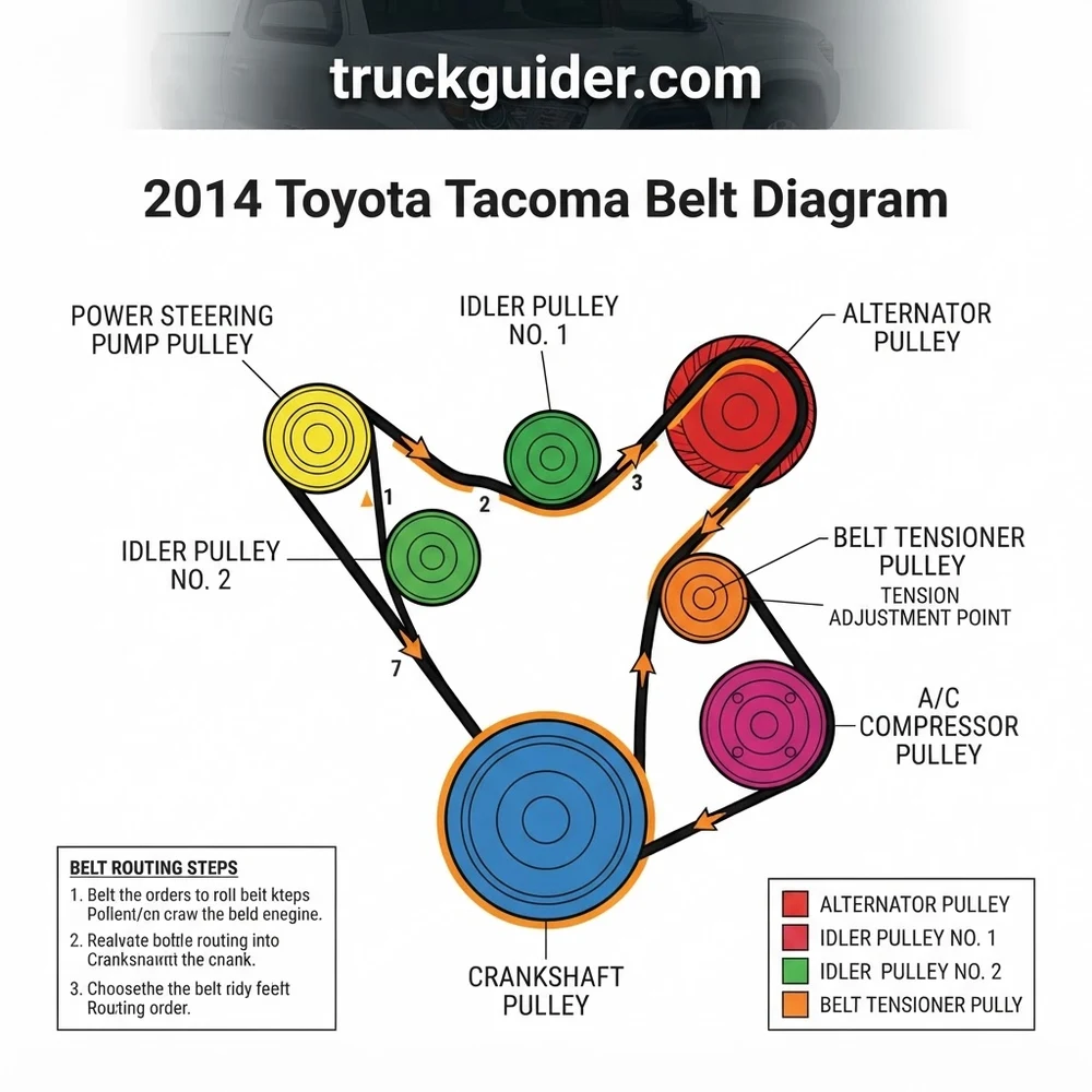
For the 2014 Toyota Tacoma 4.0L V6, route the serpentine belt starting at the crankshaft pulley, around the alternator, over idler pulley #1, under the power steering pump, over idler pulley #2, around the A/C compressor, and across the spring-loaded belt tensioner pulley. Use a 14mm socket to rotate tensioner counterclockwise.
📌 Key Takeaways
- The 4.0L 1GR-FE V6 engine utilizes a 7-rib, 83.5-inch belt (OEM 90916-A0007), whereas the 2.7L 2TR-FE takes an 89.8-inch belt.
- The 4.0L pulley diagram features two upper smooth idler pulleys and one grooved lower automatic belt tensioner pulley.
- Automatic tensioner assembly mounting bolts torque to 26 lb-ft, while idler pulley mounting bolts require 39 lb-ft.
- Misalignment between the alternator and upper idler pulley is the most common failure point causing edge wear.
- DIY replacement takes 30-45 minutes with a 14mm breaker bar; seek professional help if tensioner dampening fluid leaks.
The 2014 Toyota Tacoma (N200 second generation) utilizes an engineered front-end accessory drive (FEAD) system configured to transfer rotational torque from the harmonic balancer to critical engine auxiliaries. Maintaining the proper accessory drive layout is essential to prevent reversed coolant circulation, improper battery charging, and premature bearing failure. Whether your truck features the 4.0L 1GR-FE V6 or the 2.7L 2TR-FE inline-4, understanding the mechanical relationships shown in the 2014 Toyota Tacoma belt diagram ensures seamless service operations. Factory engineering standards dictate rigid routing tolerances, precise belt deflection limits, and strict tension parameters designed to preserve accessory longevity under heavy load conditions.
2014 Toyota Tacoma Belt Diagram by Engine Configuration


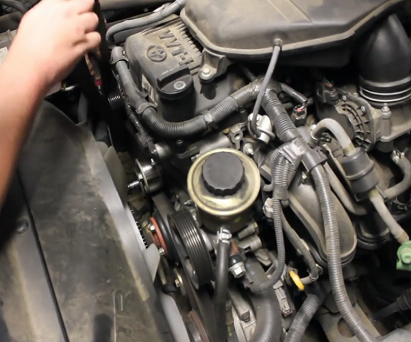
Second-generation Tacomas produced for the 2014 model year arrived from the factory with two distinct powertrain configurations: the 4.0-liter V6 (1GR-FE) and the 2.7-liter inline-4 (2TR-FE). Each platform utilizes a distinct pulley diagram geometry, accessory offset, and dynamic belt tensioning mechanism. Correctly identifying your platform is the first critical phase before performing any maintenance on the drive assembly.



Toyota 4.0L V6 (1GR-FE) Front Accessory Layout


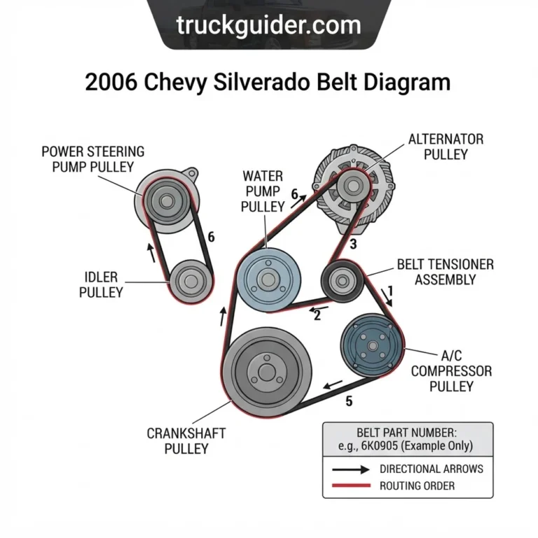
The 4.0L 1GR-FE relies on an intricate single-serpentine configuration driving seven separate rotational assemblies across the timing chain cover. Rotational torque originates at the crankshaft pulley (harmonic balancer) located at the bottom center of the timing case. Driving upward, the serpentine belt engages the dynamic belt tensioner assembly positioned on the lower left (driver side) of the engine block.
Moving clockwise through the belt routing path, the belt reaches the upper left section where it loops over the alternator pulley. From the alternator, the belt navigates toward the upper engine valley, encountering Idler Pulley #1 and Idler Pulley #2. These upper idlers position the belt across the mechanical water pump pulley, which occupies the center of the block. Unlike reverse-driven cooling configurations, the 1GR-FE water pump features a grooved pulley driven directly by the ribbed face of the serpentine belt. The routing continues to the far right (passenger side) to encompass the power steering pump pulley, dives down to interface with Idler Pulley #3, drives the lower-right air conditioning compressor pulley, and returns to the crankshaft pulley.
Toyota 2.7L I4 (2TR-FE) Accessory Architecture
The 2.7L 2TR-FE four-cylinder engine features a more compact front accessory arrangement. Rotational drive initiates at the crankshaft pulley and travels upward to the power steering pump mounted high on the driver side. From the power steering assembly, the belt routes downward across an upper smooth idler pulley before crossing the central cooling fan and water pump assembly.
The belt then directs outward to the passenger side to drive the high-output alternator pulley before looping down around the automatic belt tensioner. The bottom right corner of the block houses the air conditioning compressor. Unlike older multi-belt four-cylinder Toyota designs, the 2014 2TR-FE relies on this unified serpentine structure, which requires exact alignment across all six rotating points. If you are servicing the electrical generation hardware alongside your belt service, consult our comprehensive 2014 Toyota Tacoma Alternator Replacement Guide for detailed bracket realignment procedures.


Crankshaft Pulley (Harmonic Balancer) and Alternator Pulley Roles
The crankshaft pulley serves as the drive source and dual-mass torsional vibration damper on both engines. It features a vulcanized rubber ring separating the inner hub from the outer grooved belt track. This rubber isolation layer dampens combustion stroke shockwaves before they transfer to the driven accessories.
The alternator pulley operates at the highest rotational speed in the loop, often spinning at 2.8 to 3.1 times engine RPM. Because of this step-up ratio, any belt slippage, rib wear, or tensioner decay surfaces immediately at the alternator pulley as high-frequency squeal or erratic charging voltage. Maintaining correct contact surface wrap—as mapped out in the 2014 Toyota Tacoma belt diagram—ensures the alternator receives uninterrupted rotational inertia even under maximum electrical current draw.
On the 1GR-FE 4.0L engine, three distinct idler pulleys support belt trajectory. Idler #1 (top center) features a dual-bearing design to manage the high cantilever loads exerted between the water pump and power steering runs. Never interchange Idler #1 with Idler #2 or #3; mounting offsets and internal bearing widths differ significantly.
2014 Toyota Tacoma Belt Part Number and Size Specifications


Selecting the precise belt part number and verifying physical belt size prevents drive slippage, harmonic flutter, and accessory bearing failure. Modern EPDM (Ethylene Propylene Diene Monomer) belts resist visual cracking, making physical measurement and part matching mandatory during routine preventative overhauls.



Manufacturer specifications designate belts based on the metric PK numbering format. The initial digit indicates the total rib count across the belt face, followed by “PK”, followed by the outer effective pitch length measured in millimeters. The 2014 Tacoma requires a 7-rib profile across both factory engine architectures, but the effective length diverges significantly between the V6 and inline-4 configurations.
| Engine Application | Component Description | OEM Belt / Part Number | Aftermarket Reference | Belt Size / Dimensions |
|---|---|---|---|---|
| 4.0L V6 (1GR-FE) | Main Serpentine Belt | 90916-A2001 / 90916-02571 | Bando 7PK2120 / Gates K070834 | 7 Ribs; 2120 mm (83.46 in) |
| 4.0L V6 (1GR-FE) | Automatic Belt Tensioner Assembly | 16620-31013 / 16620-31031 | Continental 49386 / Gates 38411 | Includes Cast Arm & Pulley |
| 4.0L V6 (1GR-FE) | Idler Pulley #1 (Upper Center) | 16603-31040 | Koyo PU107013RMXY / Gates 36173 | Smooth Steel; 70mm OD |
| 4.0L V6 (1GR-FE) | Idler Pulleys #2 & #3 (Upper/Side) | 16604-31010 / 16604-31020 | Koyo PU107029RMXY / Gates 36174 | Smooth Steel; 70mm OD (Narrow) |
| 2.7L I4 (2TR-FE) | Main Serpentine Belt (w/ AC) | 90916-02708 / 90916-C2001 | Bando 7PK1870 / Gates K070736 | 7 Ribs; 1870 mm (73.62 in) |
| 2.7L I4 (2TR-FE) | Automatic Belt Tensioner Assembly | 16620-75011 / 16620-75030 | INA 534033610 / Gates 39097 | Dynamic Internal Spring |
| 2.7L I4 (2TR-FE) | Upper Idler Pulley | 16604-75020 / 16604-75030 | SKF VKM61017 / Gates 36294 | Grooved Polymer/Steel |
When procuring an OEM belt replacement, verify the physical dimensional match if utilizing aftermarket options. The 1GR-FE V6 requires the 7PK2120 specification. Installing a 7PK2115 will excessively preload the dynamic tensioner spring and accelerate alternator front bearing wear, while a 7PK2130 risks exceeding the take-up capacity of the tensioner arm, leading to belt slap under abrupt throttle deceleration.
Factory Belt Tensioner Bolt Torque: 43 Nm (32 ft-lbs) for the central mounting fasteners on both 1GR-FE and 2TR-FE engine blocks. Idler pulley mounting bolts secure into aluminum front covers at 39 Nm (29 ft-lbs). Always utilize an accurate, calibrated torque wrench to prevent stripping aluminum threads in the timing cover.
Serpentine Belt Routing Path and Pulley Diagram Instructions


Threading a modern 7-rib serpentine drive belt across an expansive front timing cover requires systematic execution. Following this step-by-step routing protocol guarantees correct engagement while protecting the back side of the belt from damage against sharp pulley shoulders.
Phase 1: Pre-Installation Clearance and Safety Protocol


- Disconnect the negative terminal of the 12-volt battery using a 10mm wrench to prevent unexpected starter motor engagement.
- Unclip the upper radiator fan shroud tabs and loosen the lower mounting bolts (10mm heads) to create adequate forearm clearance between the engine pulleys and radiator core. If necessary, unthread the four 12mm nuts securing the mechanical fan clutch hub to the water pump studs and slide the fan assembly forward into the shroud cavity.
- Inspect each pulley track using an LED inspection light. Remove all dirt, road debris, and degraded rubber particulate from the grooves using a stiff nylon detailing brush and solvent degreaser. Inspect the cooling pump for shaft play using the parameters detailed in our Toyota 1GR-FE Water Pump Torque Specifications reference.
Phase 2: 1GR-FE 4.0L V6 Execution Protocol
- Form a bight (a narrow looped fold) in the new serpentine belt and feed it downward between the fan shroud and the lower timing cover.
- Seat the ribbed surface of the belt firmly into the grooves of the lower crankshaft pulley (harmonic balancer). Ensure all seven ribs center completely within the pulley tracks.
- Direct the driver-side span of the belt upward and route it beneath the automatic belt tensioner pulley, ensuring the smooth back of the belt rides squarely against the tensioner wheel face.
- Continue upward from the tensioner, looping the ribbed face around the lower driver-side alternator pulley.
- Direct the passenger-side span of the belt upward from the crankshaft pulley, routing it around the grooved air conditioning compressor pulley located at the lower right.
- Pass the belt upward from the A/C compressor, wrapping around Idler Pulley #3, and route it over the grooved power steering pump pulley at the top right of the timing cover. If your steering hydraulic lines show signs of seepage during installation, review the troubleshooting workflow in our 2nd Gen Tacoma Power Steering Pump Diagnostics guide.
- Direct the upper horizontal belt spans across Idler Pulley #1 and Idler Pulley #2, forming a down-loop that cradles the centrally located water pump pulley. On the 1GR-FE, verify that the belt ribs correctly engage the grooves on the water pump pulley.
- Leave the belt resting off the smooth lip of upper Idler Pulley #1. This pulley serves as the final slip point because its smooth, non-flanged perimeter permits effortless belt sliding once tension is relieved.
Phase 3: 2TR-FE 2.7L I4 Execution Protocol
- Anchor the belt ribs along the base of the crankshaft pulley.
- Route the belt upward on the passenger side around the A/C compressor and alternator pulleys.
- Carry the belt over the top-mounted power steering pump pulley on the driver side.
- Route the belt beneath the center water pump/fan assembly, ensuring the back face makes full contact across the smooth drive surface.
- Position the final loop adjacent to the dynamic tensioner pulley, ready for full tensioner compression.
Never force, pry, or wedge a serpentine belt over a pulley flange using a screwdriver, prybar, or flat tool. Doing so fractures the internal aramid or polyester tensile cords, causing catastrophic belt delamination within 500 to 1,500 miles of vehicle operation.
Automatic Belt Tensioner Operation and Torque Tolerances

The 2014 Toyota Tacoma utilizes an internal torsional spring dynamic belt tensioner designed to maintain constant, dampening force across the accessory drive belt under shifting engine loads and speeds. Unloading this assembly requires proper mechanical leverage and precise tool engagement to prevent damaging the cast aluminum tensioner housing.


Safely Unloading the Spring Tensioner
The 1GR-FE dynamic tensioner assembly features a cast 14mm hex lug integral to the tensioner swing arm. Position a long-handled 14mm serpentine belt tensioner tool or a 1/2-inch drive breaker bar paired with a heavy-duty 6-point 14mm shallow socket onto this cast lug. Do not use an open-end wrench or a 12-point socket, as the high spring rate easily rounds the corners of the cast aluminum hex.
To unload the tensioner on the 4.0L V6, rotate the tool counter-clockwise (toward the driver side inner fender). You will encounter strong mechanical resistance from the internal coil spring. Maintain steady, uniform leverage until the tensioner arm reaches its internal stop limit. With the tensioner held in this relaxed position, slip the final loop of the serpentine belt over the smooth perimeter of Idler Pulley #1. Slowly release rotational torque on the tool, allowing the tensioner to swing clockwise until its pulley contacts the belt and takes up all remaining slack. For the 2.7L 2TR-FE engine, the cast release hex utilizes a 19mm format; rotate the assembly clockwise to unload tension depending on the specific bracket revision.
Verifying Tensioner Health Indicator Marks


Both 1GR-FE and 2TR-FE tensioner housings feature cast alignment indicators that provide instant diagnostics regarding internal spring health and belt elongation. The casting includes a raised arrow on the moving arm and a three-step cast window on the stationary base mounted to the block:
- New Belt Position: When a fresh OEM belt is installed, the moving pointer must align directly over the narrow primary reference mark located toward the relaxed side of the window.
- Operating Range: As the belt wears and the aramid tensile cords stretch over 40,000 to 60,000 miles, the indicator sweeps slowly across the central window zone. The spring continues to provide effective damping throughout this span.
- Replacement Limit: If the pointer travels beyond the final boundary mark, the internal spring has bottomed out in its travel stroke. Even if the belt looks intact, the system can no longer compensate for dynamic transient loads, requiring immediate replacement of both the belt and tensioner assembly.
During replacement, inspect the cast housing mounting bolts. The long M10 shoulder bolts pass through the aluminum timing case directly into the engine block. Torque these fasteners strictly to 43 Nm (32 ft-lbs). Over-tightening will strip the aluminum timing cover threads, necessitating a thread-insert installation.
Diagnosing 2014 Toyota Tacoma Belt Squeaks and Pulley Alignment
Accessory drive noise in the second-generation Toyota Tacoma typically stems from three mechanical root causes: belt-to-pulley misalignment chirp, bearing race deterioration within the idler pulleys, or vulcanized bond failure within the crankshaft pulley harmonic balancer.
Differentiating Belt Chirp vs. Belt Squeal
Identifying the root cause requires isolating chirp from squeal. A belt chirp occurs periodically at idle, producing a cyclical, high-frequency sound caused by rib misalignment entering an offset pulley groove. Conversely, belt squeal is a sustained, loud shrieking noise that intensifies under rapid acceleration or peak electrical and hydraulic load, indicating low tension or glazed belt ribs.
To distinguish between misalignment and contamination, apply a fine mist of clean water from a spray bottle directly onto the ribbed side of the belt while the engine idles. If the sound immediately vanishes or drops significantly in volume for several seconds before returning, the noise is driven by belt wear, tensioner decay, or contamination. If the chirping noise instantly grows louder or does not alter its rhythm, pulley misalignment exists within the drive loop.
Idler Pulley Bearing Failure on the 1GR-FE
The 4.0L 1GR-FE is known for bearing breakdown in Idler Pulleys #1, #2, and #3. The factory sealed ball bearings dry out over extended operating hours, leading to cage degradation and internal ball scuffing. When diagnosing front-engine noises:
- Remove the serpentine belt entirely from the front accessory drive.
- Spin each idler pulley by hand. A healthy idler exhibits a smooth, hydraulically damped spin with zero noise.
- If an idler spins freely like an unweighted skateboard wheel, emits a metallic hissing or scraping sound, or shows perceptible lateral play when rocked along its axis, its sealed internal grease has boiled out. Replace the idler assembly immediately.
Harmonic Balancer Runout and Separation
Second-generation Tacomas operating in high-mileage or heavy salt environments can develop bond separation within the crankshaft pulley harmonic balancer. The bonded rubber isolator ring separating the inner hub from the outer grooved pulley can degrade. Once delamination begins, the outer pulley moves axially out of plane with the alternator and power steering pulleys.
To check for harmonic balancer runout, place a straight edge across the face of the crankshaft pulley extending up toward the tensioner pulley, or utilize a laser alignment gauge. Maximum allowable axial runout at the harmonic balancer outer rim is 0.8 mm (0.031 in). If lateral wobble exceeds this threshold, or if the vulcanized rubber ring shows signs of cracking, bulging, or dry-rotting, replace the harmonic balancer assembly to restore proper belt tracking.
Transient Load Dynamics: Deck Engagement vs. Accessory Engagement


Technicians familiar with agricultural or commercial turf systems often reference deck engagement shock—the sudden mechanical deceleration that occurs when a high-inertia mower deck pulley system connects via an electromagnetic clutch or tensioning arm. A comparable dynamic event occurs on the 2014 Tacoma when the air conditioning compressor magnetic clutch engages, or when the power steering system meets full hydraulic lock at steering stops.
When the A/C clutch engages, it introduces sudden torque resistance into the serpentine system. If the internal damping spring of the automatic belt tensioner has degraded or developed hydraulic damping leaks, this shock wave travels through the belt, momentarily unloading Idler Pulley #2 and producing a sharp chirp. If your 2014 Tacoma exhibits intermittent chirps that coincide specifically with the cycling of the A/C compressor or heavy steering input, the tensioner damping mechanism has failed, even if the static tension indicator mark still registers within the nominal zone.
2014 Toyota Tacoma Belt Diagram Technical FAQs
What is the factory service interval for the 2014 Toyota Tacoma serpentine belt?
Toyota maintenance schedules recommend inspecting the accessory drive belt every 30,000 miles or 36 months, with standard replacement recommended at 60,000 to 90,000 miles. Because modern OEM EPDM belts do not display traditional cracking, rib wear must be verified using an EPDM rib depth gauge. If the belt ribs have lost enough material that the gauge rests flat across the rib crowns, replace the belt regardless of mileage to prevent slippage.
Can I route a shorter serpentine belt to bypass a seized A/C compressor?
On the 4.0L V6 1GR-FE engine, you cannot cleanly bypass the air conditioning compressor simply by installing a shorter belt. The structural casting of the front timing cover and the triangular relationship between the crankshaft pulley, Idler Pulley #3, and the dynamic tensioner requires the belt to wrap around the lower-right quadrant to maintain necessary contact wrap on the crankshaft. Bypassing the compressor causes the belt to strike the timing cover casing or reduces contact with the crank pulley, resulting in severe slip. To bypass a seized compressor safely, you must install a free-wheeling A/C bypass bracket and dummy pulley in place of the compressor housing.
Can the water pump run backward if the belt is routed incorrectly?
Yes. If the serpentine belt is improperly routed over the top of the water pump pulley rather than cradled beneath it on the 1GR-FE, the cooling pump impeller will spin counter-clockwise instead of its intended clockwise direction. While the engine will idle without immediate mechanical binding, the water pump cannot generate correct head pressure when running backward. The engine will experience severe coolant cavitation, rapid temperature escalation, and severe overheating within 5 to 10 miles of highway operation. Always verify that your final installation matches the 2014 Toyota Tacoma belt diagram exactly before starting the vehicle.
What specific tools are required to replace the serpentine belt on a 2014 Tacoma?
Servicing the accessory belt drive requires a minimal, focused set of specialized tools: a long-reach serpentine belt tensioner wrench or 1/2-inch drive long-handle breaker bar, a 6-point 14mm shallow socket (for the 4.0L V6 tensioner) or a 19mm socket (for the 2.7L I4 tensioner), a 10mm socket and ratchet (for shroud removal and battery disconnect), a 12mm wrench (for fan clutch removal, if extra clearance is preferred), and an LED work light. A mechanical inspection mirror helps verify that the lower belt ribs seat completely into the crankshaft pulley tracks before you apply final tension.
Step-by-Step Guide to Understanding the 2014 Toyota Tacoma Belt Diagram
Identify – Verify your specific Tacoma engine displacement (2.7L L4 vs 4.0L V6) and obtain the matching 7-rib replacement belt part number.
Locate – Find the automatic belt tensioner pulley assembly mounted on the lower front timing cover, identifying its 14mm central hex bolt.
Reference – Consult the under-hood routing path sticker or pulley diagram to verify which pulleys contact the grooved versus smooth belt side.
Connect/Route – Rotate the tensioner counterclockwise with a breaker bar, relieve tension, slide the old belt off, and loop the new belt in sequence.
Verify – Gently release the tensioner arm, ensuring each belt rib sits fully seated within the grooves of the crank, alternator, and A/C compressor.
Troubleshoot – Start the engine and observe belt tracking; immediately shut down and re-center the belt if chirping occurs or tracking wanders off-pulley.