2015 Ford F150 Exhaust System Diagram: Component Breakdown 2026

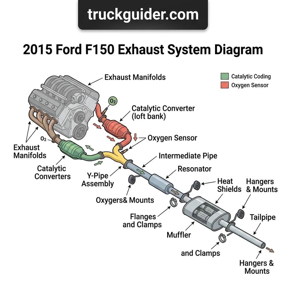
The 2015 Ford F150 exhaust system layout features a dual-bank manifold collector leading to the catalytic converters, mid-pipe assembly, resonator, and a single or dual-exit muffler configuration. Key structural points include upstream/downstream O2 sensors and flanged connections secured by M10x1.5 studs, typically requiring 35-40 lb-ft of torque for flange integrity.
📌 Key Takeaways
- Exhaust flange nuts require 35-40 lb-ft of torque to prevent leaks.
- The system structure includes four O2 sensors (two upstream, two downstream).
- High-heat anti-seize is mandatory on all manifold-to-pipe hardware.
- The resonator is the most common point for internal baffle degradation.
- Professional exhaust welding is recommended if the cat-back structural integrity is compromised by heavy rust.
Effective management of engine emissions and backpressure relies on a deep understanding of the 2015 Ford F150 exhaust system diagram. Whether you are performing a routine muffler replacement or diagnosing a persistent exhaust leak, navigating the complexities of the aluminum-body F150 chassis requires precision. This vehicle platform utilizes various engine configurations, including the 2.7L EcoBoost, 3.5L EcoBoost, 3.5L Ti-VCT, and the 5.0L Coyote V8, each dictating a specific routing structure. By mastering the schematic layout and component interactions, technicians can ensure optimal fuel economy, catalytic converter longevity, and engine performance. This guide provides the technical blueprint required to troubleshoot and maintain the exhaust architecture of the 2015 model year.
2015 Ford F150 Exhaust System Diagram: Component Breakdown
Recommended Best Deal Products


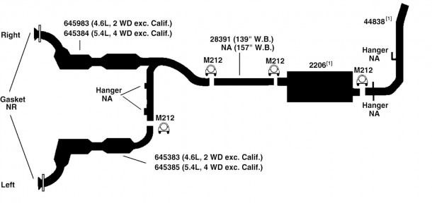
The 2015 Ford F150 exhaust system is a sophisticated assembly designed to reduce noise, neutralize harmful emissions, and optimize scavenging. Understanding the 2015 Ford F150 exhaust system diagram begins with identifying the flow path from the cylinder heads to the rear exit. Each component is engineered to operate within specific thermal ranges, and failure of any single part can trigger OBD-II diagnostic trouble codes (DTCs) related to the oxygen (O2) sensor feedback loop.
| Component | Primary Function | Troubleshooting Indicator |
|---|---|---|
| Exhaust Manifold | Directs gases from cylinders | Ticking sound on cold start |
| Catalytic Converter | Chemical emissions reduction | P0420/P0430 fault codes |
| Resonator | Cancels drone frequencies | Increased interior cabin drone |
| Muffler | Broadband noise attenuation | Visible corrosion or internal rattling |
The exhaust manifold serves as the intake point for the entire system. On the V8 5.0L configuration, these are cast units that bolt directly to the cylinder heads, while EcoBoost variants integrate the manifold into the turbocharger housing. Following the manifold, the Y-pipe or H-pipe configuration collects exhaust streams. This section is critical because it houses the primary catalytic converters. OEM specifications for the 2015 model require these converters to reach an operating temperature of approximately 400 to 600 degrees Celsius to effectively catalyze pollutants.
Downstream from the converters, the resonator serves a specialized purpose. Unlike a muffler, which uses internal chambers to reflect and dissipate sound energy, the resonator is a straight-through or expansion chamber design specifically tuned to eliminate drone at highway cruising RPMs. The muffler is the final primary silencing unit. In the 2015 F150, the muffler is typically a large, multi-chambered steel component mounted forward of the rear axle. The tailpipe routing is determined by the wheel base—SuperCrew models with a 6.5-foot bed require different piping lengths compared to the SuperCab 6.5-foot bed configuration.
Always check the oxygen sensor bungs during visual inspections. The 2015 system utilizes four sensors: two upstream (narrowband/wideband depending on engine) and two downstream, which monitor catalytic efficiency. A damaged bung or cross-threaded sensor hole can cause air leaks, triggering a lean-condition DTC.
Understanding 2015 Ford F150 Exhaust Layout by Wheelbase and Engine

The physical layout of the 2015 F150 exhaust is highly modular, but it is strictly governed by the vehicle’s frame dimensions. Because Ford utilized a variety of cab and bed lengths, the exhaust pipe segments vary in length and hanger placement. When referencing a 2015 Ford F150 exhaust system diagram, you must align the schematic with your specific wheelbase.
| Wheelbase | Configuration Type | Exhaust Note Characteristics |
|---|---|---|
| 122.4 in | Regular Cab / 6.5′ Bed | Shortest pipe runs; minimal backpressure |
| 141.1 in | SuperCab / 6.5′ Bed | Standard routing; moderate drone management |
| 145.0 in | SuperCrew / 5.5′ Bed | Most common configuration; complex hangers |
| 156.8 in | SuperCrew / 6.5′ Bed | Extended mid-pipe sections; prone to vibration |
The engine block type dictates the initial exit angle of the manifold. For the 5.0L Ti-VCT, the exhaust manifolds exit toward the rear and downward, meeting the Y-pipe near the transmission bellhousing. Conversely, the EcoBoost engines feature turbocharger outlets that force the exhaust into the catalytic converters immediately. The chassis frame rails provide the mount points for the rubber exhaust hangers. In the 2015 model, Ford switched to a lighter, aluminum-intensive design; consequently, vibration dampeners are placed strategically along the pipe length to prevent harmonic resonance from traveling into the aluminum cab structure.
When performing modifications or repairs, verify your wheelbase (found on the door jamb sticker) to ensure the intermediate pipe sections match the OEM specification. Installing an exhaust section meant for a 145-inch wheelbase on a 156.8-inch chassis will result in alignment failures at the rear hanger mounts, leading to increased stress on the flex-pipe joints and potential premature failure of the catalytic converter flanges.
How to Replace 2015 Ford F150 Exhaust System Parts
Recommended Best Deal Products


Replacing exhaust components on an F150 requires a systematic approach to prevent secondary damage to sensors or frame mounts. Before starting, apply a high-quality penetrating oil to all flange bolts and hanger pins. Given the age of these vehicles, the heat cycling often fuses hardware, making impact tools risky if used without proper lubrication.
1. Disconnect the negative battery terminal to protect sensitive ECM electronics during oxygen sensor removal.
2. Unplug the downstream O2 sensors from the wiring harness and remove them using a 7/8-inch (22mm) sensor socket.
3. Support the exhaust assembly using jack stands before loosening any hangers. The weight of the muffler and resonator is significant; falling segments can damage the aluminum undercarriage.
4. Remove the rubber hanger isolators. Use a dedicated hanger removal tool to avoid tearing the rubber bushings.
5. Loosen the flange bolts connecting the intermediate pipe to the catalytic converter. These bolts are often seized; use a 6-point socket and a long-handled ratchet or breaker bar.
6. Slide the exhaust assembly backward and clear of the frame rails.
7. Transfer any salvageable hangers or thermal heat shields to the new components before installation.
8. Install the new segments in reverse order. Always use new flange gaskets, as reused gaskets rarely seal correctly against pitted surfaces.
9. Torque all flange bolts to 40-45 lb-ft, ensuring even pressure across the gasket surface to prevent exhaust leaks.
Do not use an open flame to heat stuck bolts on the exhaust system. The fuel lines and electrical harness run in close proximity to the chassis rails. Excessive heat can also damage the ceramic substrate inside the catalytic converter, causing immediate internal failure.
Troubleshooting 2015 Ford F150 Exhaust System Diagram Issues
Performance issues often manifest as unusual noises or a drop in engine efficiency. By comparing your truck’s behavior against the standard 2015 Ford F150 exhaust system diagram, you can narrow down the culprit.
Exhaust Manifold Gasket Leaks: Characterized by a rhythmic ticking noise that increases in frequency with engine RPM, particularly during cold starts. As the manifold metal expands with heat, the leak may diminish. Replace the gaskets and check the studs for shearing, a common issue on the 5.0L engine.
Resonator Drone or Vibration: If you hear a deep, annoying hum between 1,500 and 2,000 RPM, check the resonator. If a resonator delete was performed, the natural frequency of the engine is no longer being cancelled, which is a common complaint in modified 3.5L EcoBoost F150s.
Catalytic Converter Restriction: If the vehicle lacks power under load and exhibits a burning sulfur smell, the catalyst may be clogged. Use an infrared thermometer to compare the temperature at the inlet and outlet of the converter. A properly functioning converter should be hotter at the outlet than the inlet. If the inlet is significantly hotter, the unit is restricted.
Flange Leaks: Often identified by soot deposits around the junction points. These indicate a failed gasket or rusted-out flange lip. Use a smoke machine to confirm the leak location while the system is cold.
* Oxygen Sensor Lazy Signal: If the system is otherwise sound but you receive a P0420 code, the sensor may be “lazy” (slow to switch voltage). Monitor the O2 sensor voltage in a live-data scanner; the downstream sensor should show a relatively flat line compared to the oscillating upstream sensors.
Oxygen Sensor Torque: 30 lb-ft (41 Nm). Ensure anti-seize compound is applied to the threads but keep it off the sensor tip, as silicon contamination will ruin the ceramic element.
2015 Ford F150 Exhaust System Diagram Questions Answered
Recommended Best Deal Products


Do all 2015 F150 engines use the same exhaust manifold gaskets?
No. The 2015 F150 engine lineup is diverse. The 5.0L V8 uses a different gasket footprint compared to the 3.5L EcoBoost and 2.7L EcoBoost. Always verify part compatibility by engine code (e.g., the ‘G’ code for 5.0L) rather than just the model year.
Can I perform a resonator delete to improve engine sound?
While many owners perform a resonator delete for a more aggressive exhaust note, it is important to understand the acoustic impact. Removing the resonator will introduce significant cabin drone at cruising speeds. If you proceed, ensure the remaining muffler is capable of handling the increased acoustic energy, or you may find the interior noise levels fatiguing.
Is it necessary to reset the PCM after replacing a catalytic converter?
Yes. Replacing a catalytic converter on a 2015 F150 should be followed by a KAM (Keep Alive Memory) reset or a clear of the stored emission readiness monitors. The PCM has “learned” the inefficiency of the previous converter, and resetting the memory allows the engine management system to recalibrate fuel trims based on the new, efficient data stream from the downstream sensors.
What causes the “ticking” sound that goes away as the engine warms up?
This is almost always a sign of a leaking exhaust manifold gasket or a broken manifold stud. On the 2015 5.0L V8, the manifold studs are prone to snapping due to thermal expansion cycles. When the engine is cold, the gap allows exhaust gas to escape (the ticking sound). As the metal components expand, the gap closes, and the sound disappears. Immediate repair is recommended to prevent localized heat damage to the cylinder head surface.
Step-by-Step Guide to Understanding the 2015 Ford F150 Exhaust System Diagram
Identify – Locate the specific failed component using the diagram labels.
Locate – Access the flange connections and hanger points from under the vehicle.
Reference – Cross-check the diagram to determine the correct pipe layout and clearance.
Connect/Route – Secure all exhaust piping components following the original structural path.
Verify – Perform a leak test while the engine is cold and check for proper torque specs.
Troubleshoot – Check for error codes if the O2 sensors were disconnected during the process.