24 Valve Cummins Vacuum Line Diagram: Step-by-Step Guide
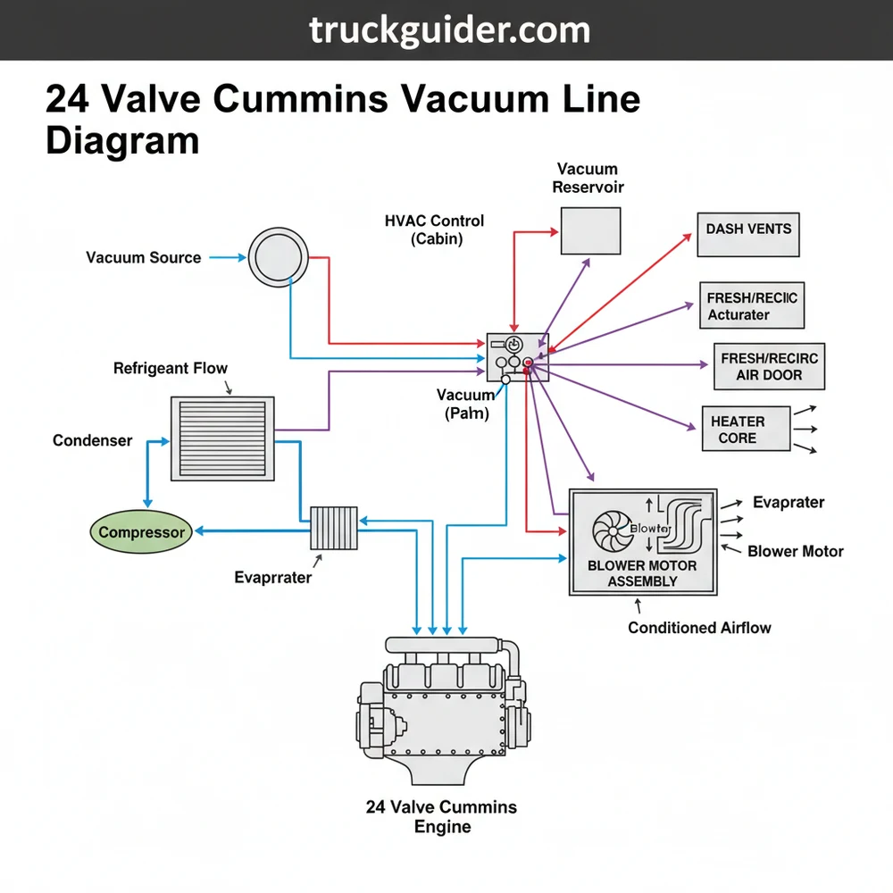
The 24 valve Cummins vacuum line diagram illustrates the routing from the engine-driven vacuum pump to the HVAC firewall connector. It shows how vacuum pressure actuates doors within the heater box, allowing the blower motor to distribute air through the evaporator and heater core based on your selected dashboard settings.
📌 Key Takeaways
- Primary purpose is to provide vacuum pressure for HVAC mode door actuation
- The vacuum pump located on the driver side is the most critical source to identify
- Always inspect lines near the battery tray for acid-induced corrosion or leaks
- A vacuum gauge is essential for verifying pressure at the firewall bulkhead
- Use this diagram when HVAC vents are stuck in the default defrost position
Understanding the intricacies of your truck’s climate control system begins with a clear 24 valve cummins vacuum line diagram. For owners of these heavy-duty machines, maintaining the pneumatic integrity of the HVAC system is vital for ensuring that air flows through the correct vents during extreme weather. Unlike modern vehicles that rely almost exclusively on electronic actuators, the 24-valve Cummins platform utilizes a mechanical vacuum pump to drive the doors within the air handler. This guide provides a comprehensive breakdown of the vacuum circuitry, helping you identify components, trace line routings, and troubleshoot common failures that lead to “defrost-only” air delivery. By mastering this diagram, you will gain the confidence to perform your own repairs and ensure your cabin remains comfortable year-round.
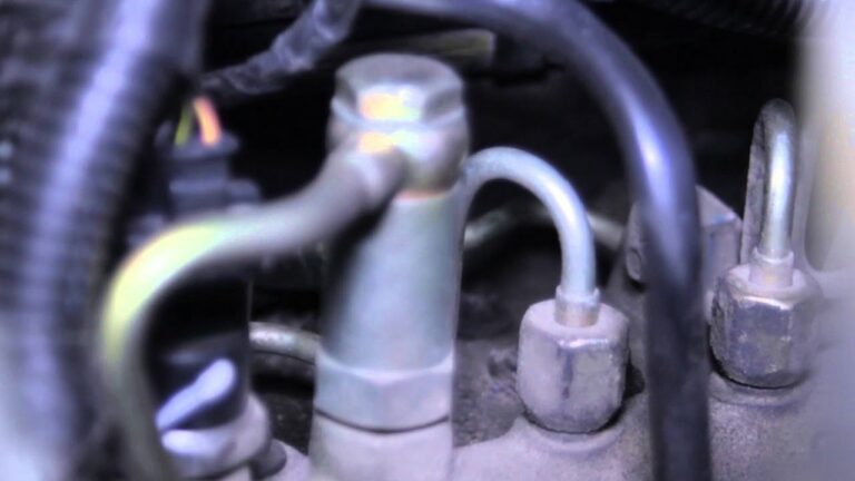
The vacuum system on a 24-valve Cummins is powered by a gear-driven pump located on the driver’s side of the engine, tucked beneath the power steering pump. This pump is the heartbeat of your HVAC controls and power brake booster.
Decoding the 24 Valve Cummins Vacuum Line Diagram
The primary 24 valve cummins vacuum line diagram is a map of pressurized and depressurized states. In this system, the vacuum originates at the mechanical pump and travels through a main supply line into a vacuum reservoir (often called a “vacuum ball”). From the reservoir, a single line passes through the firewall and connects to the back of the HVAC control head in the dashboard. The control head acts as a distribution manifold, directing vacuum to specific actuators based on the position of your vent selector knob.
The diagram is typically color-coded to assist in identification. A black line usually represents the main supply feed from the engine bay. Inside the cab, you will encounter a rainbow of smaller plastic lines. The red line typically controls the recirculation door, which determines whether the blower motor pulls fresh air from the cowl or cabin air from the return duct. The green and brown lines are usually dedicated to the floor and defrost actuators. Understanding these colors is essential because the plastic becomes incredibly brittle over time, and a single crack in a green line can result in your air conditioner blowing out of the defrost vents regardless of the setting you choose.
[DIAGRAM VISUALIZATION]
VACUUM PUMP (Engine) -> MAIN CHECK VALVE -> VACUUM RESERVOIR (Fender)
|
FIREWALL GROMMET
|
HVAC CONTROL HEAD (Switch)
/ | \
[RED] RECIRC [BLUE] MIX [GREEN] DEFROST
DOOR DOOR ACTUATOR
Detailed Breakdown of HVAC Components
📤 Share
💾 Download
To fully utilize a 24 valve cummins vacuum line diagram, you must understand the components it services. While the vacuum lines move the “doors,” the heavy lifting of cooling and heating is done by the refrigeration and coolant circuits. The blower motor is the fan that pushes air through the system. This air is forced across the heat exchanger (heater core) for warmth or the evaporator for cooling.
The air handler is the large plastic assembly under the dash that houses these components. Within this box, the vacuum actuators pull on metal or plastic rods to open and close flaps. For example, when you select “Max AC,” the vacuum system pulls the recirculation door shut, closing off the outside air intake and forcing the blower motor to pull air from the return duct inside the cab. This air is then pushed through the evaporator, where the refrigerant (circulated by the compressor and cooled by the condenser) absorbs the heat.
Do not attempt to test vacuum lines with high-pressure shop air. The actuators are designed for vacuum, not positive pressure, and you can easily rupture the internal diaphragms, necessitating a complete dashboard removal for repair.
How to Read and Interpret the Vacuum Diagram
📤 Share
💾 Download
Reading a 24 valve cummins vacuum line diagram requires a systematic approach. You aren’t just looking for lines; you are looking for the flow of energy. Follow these steps to interpret the diagram and apply it to your vehicle:
- ✓ 1. Locate the Vacuum Source: Start at the mechanical pump on the engine. The diagram will show a thick line exiting the pump.
- ✓ 2. Identify Junctions: Find the “T” fittings and check valves. Check valves are critical because they maintain vacuum in the reservoir even when the engine is under heavy load or shut off.
- ✓ 3. Trace through the Firewall: Note where the main supply line enters the cabin. This is a common failure point where the hose can rub against the metal of the firewall.
- ✓ 4. Color Match the Actuators: Look at the diagram’s legend. If your air won’t blow on your feet, find the “Floor Actuator” on the diagram and identify the corresponding line color (usually brown).
- ✓ 5. Verify Ground State: Remember that the “default” or “fail-safe” position for the Cummins HVAC system is the Defrost setting. If there is zero vacuum, all air goes to the windshield.
Step-by-Step Installation and Understanding
If you are replacing your vacuum lines or installing a new HVAC control head, follow this structured process to ensure the system functions correctly according to the 24 valve cummins vacuum line diagram.
1. Gather Necessary Tools: You will need a handheld vacuum pump with a gauge, a set of small picks for removing old lines from the control head, and high-quality silicone vacuum tubing if you are performing a full replacement.
2. Inspect the Pump and Reservoir: Before working inside the cab, verify that the engine-mounted pump is pulling at least 20 to 25 inches of mercury (Hg). Trace the line to the reservoir and ensure the reservoir isn’t cracked.
3. Access the Control Head: Remove the center bezel of your dashboard. Unscrew the HVAC control unit and pull it forward. You will see a multi-port vacuum connector plugged into the back.
4. Test Individual Actuators: Using your handheld vacuum pump, apply vacuum directly to each colored line. You should hear the corresponding door inside the air handler move. If a line doesn’t hold vacuum, that actuator or the line itself is compromised.
5. Route New Lines: If the diagram shows a line is damaged, route a new silicone line following the original path. Avoid sharp metal edges or areas near the heater core that could melt the tubing.
6. Reconnect and Test: Plug the manifold back into the control head. Start the engine and cycle through all positions (Max AC, Vent, Floor, Defrost). The transitions should be smooth and take no more than 3-5 seconds.
When replacing brittle factory lines, use 3mm or 4mm silicone vacuum hose. Unlike the hard plastic used by the factory, silicone remains flexible for decades and is much more resistant to the high under-hood temperatures typical of a Cummins turbo-diesel engine.
Common Issues & Troubleshooting with the Vacuum System
The most frequent complaint among owners seeking a 24 valve cummins vacuum line diagram is that air only blows from the defrost vents. This is a deliberate design choice; in the event of a vacuum loss, the system defaults to defrost to ensure the driver can maintain visibility. If you encounter this, use the diagram to trace the system backward from the dash to the pump.
Check for a cracked line near the battery tray. The acidic vapors from the batteries often eat through the plastic vacuum lines that run along the passenger side fender. Another common issue is the check valve. If your HVAC vents switch to defrost only when you are accelerating or towing a heavy load, your check valve is likely stuck open, allowing vacuum to bleed back toward the engine when the pump’s output is low. Finally, oil contamination can occur if the vacuum pump’s internal seals fail, drawing engine oil into the vacuum lines. This oil will eventually reach the control head and ruin the rubber seals inside the switch.
The Relationship Between Vacuum and Mechanical Cooling
While the vacuum system manages air direction, it works in tandem with the mechanical cooling components. The compressor is responsible for pumping refrigerant through the system. When you turn on the AC, the compressor sends high-pressure gas to the condenser (located in front of the radiator), where it sheds heat. From there, the refrigerant travels to the evaporator inside the air handler.
The vacuum system’s role here is to move the “blend door” and “mode doors.” However, on many 24-valve models, the blend door (which controls temperature by mixing air from the heat exchanger and evaporator) is actually controlled by an electric motor, not a vacuum actuator. It is a common misconception that “no heat” is a vacuum issue. In reality, if you have air flowing from the correct vents but it isn’t the right temperature, the problem lies with the electric blend door actuator or a clogged heater core heat exchanger, rather than the 24 valve cummins vacuum line diagram circuitry.
Best Practices for Long-Term Maintenance
To prevent the need for a total system overhaul, adopt a proactive maintenance strategy. Regularly inspect the main vacuum line that runs across the top of the firewall. This line is subject to extreme vibration from the Cummins engine and often develops hairline fractures. Applying a UV-protectant spray to the visible rubber and plastic lines can also slow down the degradation process.
When sourcing replacement parts, avoid “universal” plastic line kits. Instead, look for high-quality components specifically designed for automotive heat cycles. If your vacuum pump is showing signs of weakness (less than 15 inches of Hg), rebuild kits are available and are much more cost-effective than replacing the entire pump assembly. Keeping your return duct filters clean (if equipped) also reduces the strain on the blower motor and helps maintain consistent air pressure against the vacuum-operated doors.
If your truck has four-wheel drive, the vacuum system also controls the Central Axle Disconnect (CAD). A leak in the 4WD lines will cause your HVAC system to malfunction, so always check the lines running down to the front axle when troubleshooting.
Summary of Vacuum Circuitry Benefits
A functioning vacuum system is the difference between a frustrating drive and a comfortable journey. By utilizing the 24 valve cummins vacuum line diagram, you remove the guesswork from repairs. You can quickly identify why the air isn’t reaching the floor vents or why the recirculation door isn’t closing to keep out exhaust fumes. This system, while seemingly antiquated, is incredibly reliable if the integrity of the lines is maintained.
Whether you are restoring an older truck or just performing routine maintenance, understanding how the vacuum pump interacts with the air handler and its internal components like the evaporator and heat exchanger is vital. With a clear diagram and a basic understanding of pneumatic principles, you can keep your Cummins HVAC system operating at peak performance for hundreds of thousands of miles. Remember to always start at the source and work your way through the firewall to the control head; most problems are simple leaks that can be fixed with a few inches of new tubing and a clear understanding of the vacuum path.
Frequently Asked Questions
Where is the vacuum pump located?
On the 24 valve Cummins, the vacuum pump is located on the driver’s side of the engine, driven by the timing gear housing. It is positioned behind the power steering pump. This pump supplies the vacuum necessary for the HVAC actuators and, on some models, the cruise control system.
What does this vacuum line diagram show?
This diagram shows the path of vacuum from the mechanical pump to the reservoir and into the cab. It highlights how vacuum is distributed to the HVAC actuators, which control whether air from the blower motor passes through the evaporator or heater core before exiting the dash vents or defrost.
How many connections does the HVAC vacuum harness have?
The main HVAC vacuum harness typically features one primary supply line entering the firewall. Once inside, it splits into five or six colored lines. these lines connect to various vacuum motors or actuators that manage the blend doors, recirculation doors, and mode doors within the interior HVAC assembly housing.
What are the symptoms of a bad vacuum line?
The most common symptom is the HVAC system defaulting to the defrost position regardless of the dash setting. You may also notice the AC compressor cycling incorrectly if vacuum-operated switches fail. Additionally, a complete loss of vacuum will prevent the blower motor from directing air to the face vents.
Can I replace these vacuum lines myself?
Yes, replacing these lines is a common DIY task. Many owners choose to replace the brittle factory plastic lines with high-quality silicone vacuum tubing. This requires basic hand tools and a vacuum diagram to ensure each actuator is reconnected to its corresponding port on the dash selector switch.
What tools do I need for vacuum line repair?
You will need a hand-held vacuum pump with a gauge for testing individual actuators and line integrity. Additionally, have a set of small hose cutters, various T-fittings, and needle-nose pliers. These tools allow you to diagnose leaks and ensure the refrigerant-cooled air is directed through the evaporator correctly.

![3.6 Pentastar Oil Type & Capacity Guide (2011: Specs & Fitment Guide [2026]](https://truckguider.com/wp-content/uploads/2026/03/3-6-pentastar-oil-type-featured.webp)