Alpine Stereo Wiring Diagram: Easy Setup Guide
An alpine stereo wiring diagram maps the specific color-coded leads for power, speakers, and accessories. It identifies the ground wire for safety, the hot wire for battery memory, and the neutral wire or accessory lead for ignition power. This guide helps you correctly route every traveler wire to ensure your head unit operates correctly.
📌 Key Takeaways
- Provides a visual roadmap for car audio harness color codes
- Identify the harness connector to prevent electrical shorts
- Always disconnect the vehicle battery before touching the hot wire
- Use high-quality crimp connectors for vibration-resistant bonds
- Use this diagram when upgrading from a factory head unit
Installing a high-performance head unit requires precision, and having an accurate alpine stereo wiring diagram is the first step toward achieving a professional-grade audio setup. Whether you are upgrading an older vehicle or installing a flagship digital media receiver, understanding how to map the harness to your vehicle’s electrical system is crucial for safety and sound quality. This guide provides a comprehensive breakdown of standard Alpine wire colors, pin locations, and connection sequences. By following this technical walkthrough, you will learn how to identify power leads, speaker outputs, and secondary trigger wires to ensure your system functions perfectly without blowing fuses or damaging sensitive internal components.
Most Alpine head units utilize a standard 16-pin molex connector. While the wire colors generally follow the EIA (Electronic Industries Alliance) standards, always verify the pinout on your specific model’s chassis sticker before finalizing connections.
Understanding the Alpine Stereo Wiring Diagram Layout
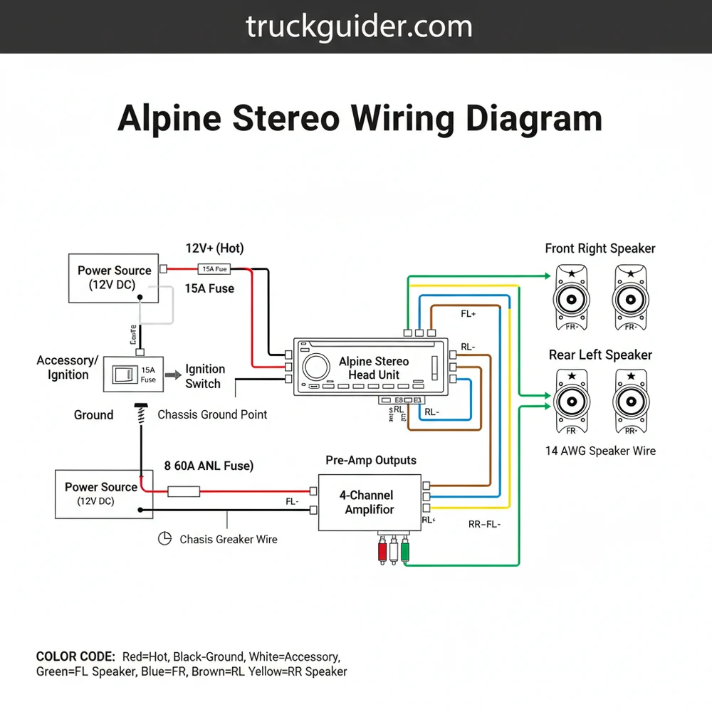
The alpine stereo wiring diagram serves as the master map for your head unit’s electrical interface. Unlike residential wiring where you might encounter a traveler wire or a common terminal on a 3-way switch, automotive audio systems operate on a 12V DC (Direct Current) architecture. The diagram is typically divided into three primary sections: the power delivery system, the speaker output array, and the auxiliary control leads.
At the center of the diagram is the main 16-pin wiring harness. The top row of pins usually handles the primary power and ground connections, while the bottom row manages the speaker channels. Alpine uses a very specific color-coding system that has remained remarkably consistent over decades. The hot wire, which provides constant 12V voltage to maintain memory settings like radio presets and clock time, is always yellow. The ignition or “switched” wire is red, which tells the unit to power on when the key is turned.
Proper grounding is the most critical aspect of the diagram. The ground wire, which is solid black, must be connected to a clean, unpainted metal surface on the vehicle’s chassis. In home electrical systems, you might refer to a neutral wire or a brass screw on a receptacle to complete a circuit, but in a car, the entire metal frame acts as the common terminal for the negative side of the battery.
The visual diagram also illustrates the speaker wire pairs. Each of the four speakers (Front Left, Front Right, Rear Left, Rear Right) has two wires: a solid color for the positive terminal and the same color with a black stripe for the negative terminal. For example, the white wire is the Front Left positive, while the white wire with a black stripe is the Front Left negative. This symmetry is vital for maintaining phase. If you accidentally swap the positive and negative on one speaker, it will play “out of phase,” resulting in a significant loss of bass response and a hollow sound stage.
Comprehensive Wire Color and Function Reference
📤 Share
💾 Download
To interpret an alpine stereo wiring diagram effectively, you must be familiar with the standardized color codes used across their product line. Understanding these ensures that the voltage is distributed correctly and that triggers are sent to the right components, such as external amplifiers or power antennas.
- ✓ Yellow (Constant 12V / Hot Wire): Connects directly to the battery or a constant power fuse. It maintains memory and provides the main current for the internal amplifier.
- ✓ Red (Switched 12V / Accessory): Connects to the ignition circuit. This wire triggers the unit to wake up when the vehicle is started.
- ✓ Black (Ground Wire): The return path for the electrical circuit. It must be secured to the chassis.
- ✓ Blue/White (Remote Turn-On): Sends a low-voltage signal to turn on external amplifiers or signal processors.
- ✓ Orange/White (Illumination): Connects to the vehicle’s dimmer circuit, allowing the stereo screen to dim when the headlights are turned on.
- ✓ White & White/Black: Front Left Speaker (+ and -).
- ✓ Gray & Gray/Black: Front Right Speaker (+ and -).
- ✓ Green & Green/Black: Rear Left Speaker (+ and -).
- ✓ Purple & Purple/Black: Rear Right Speaker (+ and -).
Step-By-Step Installation Guide
📤 Share
💾 Download
Following an alpine stereo wiring diagram requires a methodical approach to ensure every connection is secure and insulated. Before beginning, ensure you have a high-quality wire stripper, a crimping tool or soldering iron, and heat-shrink tubing.
Step 1: Disconnect the Battery
Safety is paramount. Before touching any wires, disconnect the negative terminal of your vehicle’s battery. This prevents accidental short circuits that could blow expensive fuses or damage the vehicle’s ECU. In automotive electrical work, failing to disconnect the power is the most common cause of installation failure.
Step 2: Prepare the Harnesses
You will have two main harnesses: the Alpine harness that came with your stereo and a vehicle-specific adapter harness that plugs into your car’s factory plug. Strip about half an inch of insulation from each wire on both harnesses. If you notice a wire is a significantly thinner gauge than the others, handle it with care to avoid snapping the internal copper strands.
Step 3: Connect the Power and Ground
Match the yellow wire from the Alpine harness to the yellow wire on the adapter harness. Repeat this for the red wires. Next, focus on the black ground wire. While the adapter harness may have a black wire, it is often best practice to ground the Alpine unit directly to a metal bolt on the dashboard frame. Ensure the connection is tight and free of rust or paint.
Step 4: Map the Speaker Connections
Using your alpine stereo wiring diagram, match the four pairs of speaker wires. It is helpful to work on one speaker at a time to avoid confusion. For instance, take the green and green/black wires and connect them to their corresponding partners on the adapter harness. Use crimp caps or solder the joints for a permanent, vibration-resistant connection.
When connecting the blue/white remote turn-on wire, if you are not using an external amplifier, wrap the end in electrical tape or heat shrink. If this wire touches metal while the unit is on, it can short out the internal remote-trigger circuit, requiring a professional repair.
Step 5: Address Specialty Wires
Many modern Alpine units include a bright yellow/blue wire for the parking brake. This is a safety feature that prevents video playback unless the vehicle is parked. This wire must be tapped into the positive side of the parking brake switch. Additionally, if your vehicle has a power antenna, connect the solid blue wire from the Alpine harness to the antenna trigger wire.
Step 6: Insulate and Organize
Once all connections are made according to the alpine stereo wiring diagram, inspect every joint. There should be no exposed copper. Use heat-shrink tubing to provide a durable seal against moisture and heat. Bundle the wires neatly using zip ties to prevent them from rattling against the plastic dashboard components once the unit is installed.
Step 7: Final Test and Mounting
Plug the harness into the back of the Alpine unit and reconnect the vehicle battery. Turn the ignition to the “ACC” position. The unit should power up. Test the balance and fader settings to ensure the front-left speaker is actually the front-left speaker. If everything sounds correct, slide the unit into the mounting sleeve and secure the trim.
Common Issues and Troubleshooting
Even with a detailed alpine stereo wiring diagram, issues can arise during the installation process. Most problems stem from poor grounding or incorrect power routing.
One of the most frequent complaints is the stereo losing its memory every time the car is turned off. This happens when the red (switched) and yellow (constant) wires are swapped. The yellow wire must have constant voltage to keep the memory chip active. If the stereo only works when the headlights are on, you have likely miswired the illumination or dimmer wire into a power circuit.
Another common issue is “engine whine,” a high-pitched noise that follows the RPM of the motor. This is usually caused by a ground loop. Check your black ground wire; it should be as short as possible and connected to a solid metal point. Avoid using a common terminal that already has multiple other ground wires attached to it, as this can introduce electrical interference.
Never replace a blown fuse with one of a higher amperage. If your Alpine unit keeps blowing the 10A or 15A fuse on the back of the chassis, there is a short circuit in your wiring. Increasing the fuse size can lead to an electrical fire or permanent damage to the stereo’s motherboard.
Tips and Best Practices for a Professional Install
To get the most out of your alpine stereo wiring diagram, consider the environment of a car. Unlike a home where wires stay stationary, a vehicle is a high-vibration environment with extreme temperature swings.
First, pay attention to wire gauge. If you are running new power lines directly to the battery for a high-output Alpine head unit, use a thicker gauge (typically 12 or 14 AWG) to ensure stable voltage delivery. Thin wires create resistance, which leads to heat and a loss of audio clarity during high-volume peaks.
Second, use the right connectors. While twisting wires together and using electrical tape is common in amateur installs, it is prone to failure. Use nylon-insulated butt connectors or, ideally, solder and heat-shrink. This creates a connection that is effectively a single piece of metal, ensuring the signal remains pure.
Third, check for a “phantom” traveler wire effect. In some luxury vehicles with factory-amplified systems (like Bose or Harman Kardon), the wiring harness doesn’t just send audio; it sends data signals. In these cases, a standard alpine stereo wiring diagram might not be enough. You may need a digital interface module to translate the Alpine’s analog output into the vehicle’s digital data bus.
Finally, invest in quality components. Alpine units are known for their high-voltage RCA pre-outs. If you are using an external amplifier, use high-quality shielded RCA cables and run them on the opposite side of the vehicle from the main power wires to prevent electromagnetic interference.
Conclusion
Successfully navigating an alpine stereo wiring diagram is the difference between a frustrating afternoon and a premium audio experience. By understanding the specific roles of the hot wire, the ground wire, and the various speaker outputs, you can transform your vehicle’s cockpit into a high-fidelity listening environment. Always prioritize solid connections, proper grounding, and thorough insulation. With the right tools and a methodical approach to the 16-pin harness, your Alpine head unit will provide years of reliable, high-quality performance. Remember, the diagram is your roadmap; following it precisely ensures that every watt of power and every decibel of sound is delivered exactly as the engineers intended.
Step-by-Step Guide to Understanding the Alpine Stereo Wiring Diagram: Easy Setup Guide
Identify the individual wires on your Alpine harness and match them to the wiring diagram.
Locate the black ground wire and secure it to the common terminal or a metal chassis point.
Understand how the yellow hot wire connects to a constant 12V source for station memory.
Connect the speaker wire pairs to their corresponding neutral wire or negative return leads.
Verify that the blue/white traveler wire is connected if you are using an external amplifier.
Complete the installation by securing all connections with electrical tape or heat shrink before mounting.
Frequently Asked Questions
Where is the Alpine stereo harness located?
The Alpine stereo harness is located directly at the rear of the head unit. It plugs into a dedicated port on the stereo chassis and splits into several colored leads that connect to your vehicle’s factory wiring or an aftermarket adapter harness to provide power and audio signals.
What does an alpine stereo wiring diagram show?
This diagram displays the color-coding standards used by Alpine, such as yellow for constant power, red for ignition, and black for the ground wire. It illustrates where each speaker lead connects and identifies auxiliary wires like the blue/white traveler wire used for remote amplifier turn-on signals.
How many wires does an Alpine stereo harness have?
A standard Alpine harness typically has 14 to 16 wires. This includes four pairs of speaker wires, a hot wire for constant 12V power, an accessory wire for ignition, a ground wire, and additional leads for functions like dimming, power antennas, or steering wheel control interfaces.
What are the symptoms of a bad stereo connection?
Symptoms of a poor connection include the stereo failing to turn on, intermittent power loss when driving over bumps, or speakers producing static. If the hot wire is loose, you may lose your radio presets every time the vehicle is turned off, indicating a memory power failure.
Can I install an Alpine stereo myself?
Yes, you can install an Alpine stereo yourself using a wiring diagram and a vehicle-specific harness adapter. By matching the colors on the Alpine harness to the adapter, you can create a plug-and-play solution that avoids cutting your vehicle’s factory wires, making the installation clean and reversible.
What tools do I need for stereo wiring?
You will need a wire stripper, a crimping tool, and butt connectors or solder with heat shrink tubing. A multimeter is also recommended to verify which lead is the hot wire and which is the ground wire if you are troubleshooting an older vehicle without a standard adapter.


![Best Oil Additive for Lifters: Complete Fix Guide [2026]](https://truckguider.com/wp-content/uploads/2026/03/oil-additive-for-lifters-featured.webp)