5.7 Hemi Wiring Harness Diagram: Easy Setup Guide
A 5.7 Hemi wiring harness diagram maps out the electrical connections for fuel injectors, coil packs, and sensors to the PCM. It identifies the hot wire supplying power, the ground wire for circuit completion, and signal wires. Understanding these pathways ensures proper engine timing, fuel delivery, and sensor communication.
📌 Key Takeaways
- Provides a visual map of all engine-to-PCM electrical connections
- The PCM connector is the most critical component to identify correctly
- Always disconnect the battery to prevent shorting the PCM during testing
- Use a multimeter to verify continuity across long wire runs
- Essential for engine swaps, performance tuning, or misfire diagnosis
Navigating the complexities of a modern engine requires a clear roadmap, and the 5.7 hemi wiring harness diagram serves as that essential guide for mechanics and DIY enthusiasts alike. Whether you are performing a full engine swap into a classic muscle car or troubleshooting a persistent check engine light in a late-model truck, understanding how the Powertrain Control Module (PCM) communicates with sensors is vital. This article will deconstruct the intricate web of wires, providing you with a clear understanding of pin connections, wire colors, and terminal identification. By the end of this guide, you will be equipped to identify specific circuits, test for proper voltage, and ensure your Hemi engine runs at peak performance without the frustration of electrical gremlins.
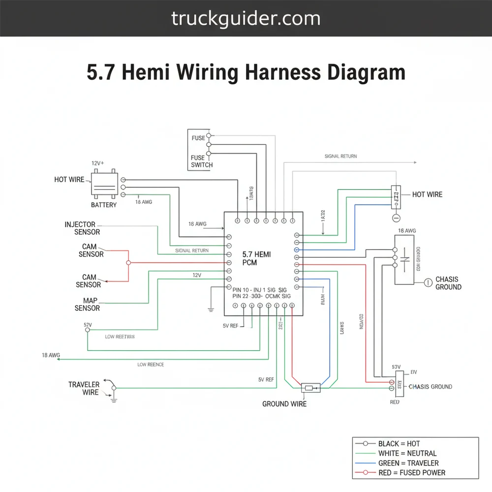
The 5.7 Hemi engine utilizes a sophisticated multi-plug PCM system, typically consisting of four main connectors (C1, C2, C3, and C4). Each connector is color-coded and keyed to prevent incorrect installation, which is critical for protecting the sensitive internal circuitry of the computer.
The primary 5.7 hemi wiring harness diagram is divided into several sub-systems, including the ignition system, fuel injection system, sensor feedback loop, and the data bus. The diagram visually represents the PCM as the central hub, with lines branching out to various components such as the Crankshaft Position Sensor (CKP), Camshaft Position Sensor (CMP), and the individual coil packs. Each line on the diagram is labeled with a specific color code (e.g., Brown/White or Dark Blue/Dark Green) and a numeric pin identifier. Understanding these labels is the first step in successful diagnostic work.
Visualizing the layout starts with the PCM connectors. The C1 connector usually handles power and ground distribution, while C2 and C3 are heavily involved in engine sensors and transmission controls. The C4 connector often manages auxiliary functions and body control interactions. In the diagram, you will notice that the wire gauge varies depending on the current load; for example, the main power feed to the fuel injectors uses a thicker gauge wire compared to the delicate 5-volt reference signal sent to the Throttle Position Sensor (TPS).
A crucial aspect of the 5.7 hemi wiring harness diagram is the identification of grounding points. Unlike residential wiring where a dedicated neutral wire is used to return current to the source, automotive systems utilize the vehicle’s chassis as a common return path. In the diagram, these are indicated by a specific ground symbol, often tied to a common terminal block on the engine block or the inner fender well. Ensuring these connections are free of corrosion is just as important as the hot wire connections themselves.
To effectively read and interpret a 5.7 hemi wiring harness diagram, you must approach the schematic with a systematic mindset. This is not merely about looking at lines; it is about understanding the flow of electrons from the source to the load and back to the ground.
- ✓ Identify the Component: Locate the specific sensor or actuator you are troubleshooting on the diagram.
- ✓ Trace the Power Source: Follow the line back to the fuse box or the PCM to see where the 12V or 5V voltage originates.
- ✓ Check the Pinout: Note the connector number and pin number at both the component end and the PCM end.
- ✓ Verify Wire Color: Match the physical wire in the harness to the color code listed on the diagram to ensure you are testing the correct circuit.
- ✓ Measure Resistance: Use a multimeter to check for continuity between the two ends of the wire.
- ✓ Test Voltage Drops: With the circuit under load, measure the voltage at the component to ensure it is receiving the necessary power.
When performing an installation or a repair using the 5.7 hemi wiring harness diagram, having the right tools is non-negotiable. You will need a high-quality Digital Multimeter (DMM), a set of back-probe pins for testing connectors without damaging the seals, wire strippers, and a soldering iron for permanent repairs. Avoid using “vampire” style tap-in connectors, as these often lead to moisture intrusion and eventual circuit failure.
Safety must be your top priority. Always disconnect the negative battery terminal before cutting or splicing into the main harness. Even a brief short-circuit can fry the delicate logic gates inside the PCM, leading to a costly replacement. Furthermore, be aware of the difference between signal wires and power wires. A signal wire may only carry 5 volts and very low amperage, while a hot wire for the starter solenoid or alternator can carry hundreds of amps.
In residential wiring, you might be familiar with a brass screw on a receptacle or a traveler wire in a three-way lighting circuit. However, in the world of the 5.7 Hemi, the hardware is very different. Connections are made via crimped pins locked into plastic housings. While the concept of a “common terminal” exists in both worlds, in your Hemi harness, this usually refers to a shared splice where multiple sensors receive their 5-volt reference or their ground wire connection. Understanding these terminologies in the correct context prevents dangerous mistakes.
Never use a test light on PCM signal wires. The current draw of a traditional incandescent test light can exceed the capacity of the PCM’s driver circuits, causing internal damage. Always use a high-impedance digital multimeter for testing sensor outputs.
Common issues involving the Hemi harness often stem from heat and vibration. Because the 5.7 Hemi generates significant heat, the plastic loom and wire insulation can become brittle over time. This leads to cracked insulation and intermittent short circuits. If your vehicle is experiencing random misfires (P0300 codes) or sensor circuit high/low codes, the wiring harness is the first place to look.
One frequent problem area is the Crankshaft Position Sensor connector. Located near the starter, it is subjected to extreme thermal cycles. If the diagram shows a 5-volt reference at the sensor but your multimeter reads 0, you likely have a break in the wire within the loom. The 5.7 hemi wiring harness diagram allows you to find the exact pin at the PCM to test for continuity, effectively “sectioning” the harness to find the fault without tearing the whole engine bay apart.
Another common failure point involves the grounding circuits. If you notice multiple sensors failing simultaneously, such as the Intake Air Temperature (IAT) and the MAP sensor, they often share a common ground wire path. By consulting the diagram, you can locate the shared splice point. If that splice has corroded or pulled loose, it will cause a “floating ground,” leading to erratic sensor readings and poor engine performance.
When troubleshooting, always check for “pin tension.” Sometimes the wiring is fine, but the female terminal inside the connector has spread open, making a poor connection with the male pin. Use a spare male pin to feel for resistance when inserting it into the connector.
To ensure long-term reliability after using the 5.7 hemi wiring harness diagram for a repair, follow these best practices. First, use heat-shrink tubing on all splices. This prevents moisture from entering the copper strands, which can lead to “wicking” where corrosion travels up the wire under the insulation. Second, ensure the harness is properly secured with factory-style clips. A harness that is allowed to rub against the valve cover or intake manifold will eventually chafe through, leading to a breakdown.
If you are performing an engine swap, consider using a standalone harness or a high-quality conversion kit. These kits simplify the 5.7 hemi wiring harness diagram by removing unnecessary circuits (like those for the original body control module) and focusing only on what the engine needs to run. This reduces the number of connections you need to manage and makes future troubleshooting much easier. When selecting components, always choose automotive-grade wire that is rated for high-temperature environments. Standard primary wire found at general hardware stores may not have the chemical and heat resistance required for an engine bay.
When implementing the wiring for a Hemi, pay close attention to the ignition coil wiring. The 5.7 Hemi uses a “waste spark” or dual-ignition setup depending on the version. This means the sequence of the wiring is paramount. Crossing the wires for coil pack #1 and #3 will result in a backfire and potential engine damage. Always double-check your connections against the diagram’s pinout list before the first start-up.
In summary, the 5.7 hemi wiring harness diagram is an indispensable asset for any technical work involving this iconic engine. By mastering the interpretation of wire colors, pinouts, and voltage signals, you move from guesswork to precision diagnostics. While automotive electrical systems differ significantly from household wiring—lacking a neutral wire or brass screw terminals in favor of sophisticated ground wire networks and weather-sealed connectors—the principles of electricity remain constant.
Maintaining the integrity of your wiring harness is the best way to ensure the longevity of your 5.7 Hemi. Regularly inspect the harness for signs of wear, especially near heat sources. If you encounter complex issues that go beyond simple continuity tests, such as CAN Bus communication errors, it may be time to consult a professional with an oscilloscope. However, for the vast majority of sensor failures and power delivery issues, a firm grasp of the wiring diagram and a steady hand with a multimeter will see you through the job successfully. With patience and the right information, you can keep your Hemi-powered vehicle running smoothly for years to come.
Step-by-Step Guide to Understanding the 5.7 Hemi Wiring Harness Diagram: Easy Setup Guide
Identify the main power sources, including the hot wire and the primary engine ground wire points.
Locate the various sensor connectors such as the MAP, cam, and crank sensors on the diagram.
Understand how the traveler wire routes signals between different modules in specialized or modified electrical setups.
Connect the fuel injector and ignition coil plugs, ensuring each follows the specific cylinder bank sequence.
Verify that every common terminal is securely seated and that there are no exposed or pinched wires.
Complete the installation by reconnecting the battery and scanning for any remaining electrical diagnostic trouble codes.
Frequently Asked Questions
Where is the 5.7 Hemi PCM located?
The Power Control Module (PCM) is typically located on the passenger side firewall or near the coolant overflow tank. This central hub manages the entire 5.7 Hemi wiring harness, receiving data from sensors to regulate ignition timing and fuel flow. Accessing it requires removing plastic covers or brackets.
What does a 5.7 Hemi wiring harness diagram show?
This diagram illustrates every electrical pathway between engine sensors and the PCM. It identifies wire colors, pin locations for the common terminal, and specific signal routes. It is essential for diagnosing broken circuits, mapping a traveler wire in custom setups, or ensuring sensors receive proper voltage and ground signals.
How many connections does the harness have?
The harness features dozens of connections, including eight fuel injectors, eight coil packs, knock sensors, and oxygen sensors. It relies on a primary hot wire for power distribution and a ground wire for circuit completion. Each connector is indexed to prevent incorrect installation and ensure a secure fit.
What are the symptoms of a bad wiring harness?
A failing harness often causes intermittent misfires, erratic sensor readings, or a complete ‘no-start’ condition. You may notice frayed insulation exposing the ground wire or melted connectors. Diagnostic trouble codes (DTCs) related to multiple sensors simultaneously often point toward harness damage rather than individual sensor failure.
Can I replace a 5.7 Hemi wiring harness myself?
Replacing a harness is a moderate DIY task that requires patience. While the connections are mostly ‘plug and play,’ routing the harness correctly behind the engine block can be difficult. Using a high-quality wiring diagram ensures every connector reaches its intended component without straining the neutral wire or signal lines.
What tools do I need for harness repair?
You will need a digital multimeter to test continuity, wire strippers, and a soldering iron for permanent repairs. A terminal release tool is helpful for depinning the common terminal if needed. Heat shrink tubing and automotive-grade electrical tape are also essential for protecting connections from engine heat.