6.4 Hemi Cooling System Diagram: Complete Layout Guide
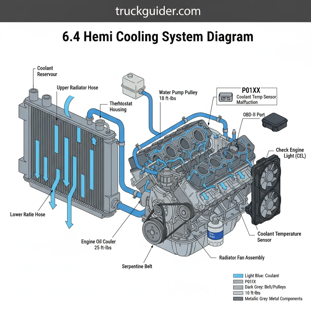
The 6.4 Hemi cooling system diagram illustrates a pressurized loop where coolant moves from the radiator to the water pump, through the engine block, and out via the thermostat housing. It highlights the integration of the heater core, expansion tank, and the various hoses required to maintain optimal operating temperatures.
📌 Key Takeaways
- Visualizes the high-flow path necessary for high-performance Hemi engines
- Identifies the thermostat and water pump as central flow regulators
- Critical for locating the air bleed screw to prevent engine hotspots
- Assists in tracing leaks in heater core lines and bypass hoses
- Essential for ensuring proper reassembly after a water pump replacement
Maintaining a high-performance engine like the 392 Apache requires a deep understanding of its thermal management. If you are a DIY mechanic or a truck enthusiast, finding a reliable 6.4 hemi cooling system diagram is the first step toward successful maintenance or repair. This diagram serves as a roadmap for the complex network of hoses, sensors, and mechanical components that prevent your engine from warping under extreme heat. In this guide, we will break down every element of the cooling circuit, from the radiator to the intricate passages within the cylinder heads. You will learn how the system regulates temperature, how it communicates with the vehicle’s computer, and exactly how to interpret the visual layout to perform professional-grade repairs at home.
Decoding the 6.4 Hemi Cooling System Diagram
The cooling layout for the 6.4-liter V8 engine is a pressurized, bypass-integrated system designed to move heat away from the combustion chambers as efficiently as possible. When looking at a 6.4 hemi cooling system diagram, the most prominent feature is the centralized water pump, which is driven by the accessory belt. The diagram typically uses color-coded paths: red or dark orange for high-temp “outbound” coolant flowing toward the radiator, and blue or green for “inbound” cooled liquid returning to the engine block.
A critical aspect of this diagram is the flow direction through the cylinder heads and the engine block. Unlike older engines that might have used a simpler parallel flow, the 6.4 Hemi utilizes a sophisticated coolant flow pattern that prioritizes the exhaust valve areas, which are the hottest parts of the head. The diagram will also illustrate the heater core circuit, which branches off from the main flow to provide cabin heat. This sub-circuit is important because even if your radiator is functioning perfectly, a blockage in the heater core lines—clearly visible on a professional diagram—can cause localized overheating issues or air pockets.
Furthermore, the diagram highlights the integration of the thermostat housing. On the 6.4 Hemi, the thermostat is located on the intake side of the water pump. This placement ensures that the engine reaches operating temperature quickly by cycling coolant through a bypass loop until the wax pellet in the thermostat melts and opens the valve to the radiator. Modern diagrams also include the locations of the temperature sensors which send data directly to the ECU, ensuring that the electric fans kick on at the precise moment required to maintain thermal equilibrium.
[DIAGRAM_PLACEHOLDER: 6.4 Hemi Cooling System Layout showing Radiator, Water Pump, Thermostat, Heater Core, and Overflow Tank with directional flow arrows]
Detailed Component Analysis and Flow Dynamics
📤 Share
💾 Download
Understanding the 6.4 hemi cooling system diagram requires more than just identifying parts; you must understand how they interact. The system begins at the radiator, where the coolant loses heat to the atmosphere. From there, the water pump pulls the cooled liquid in. It is important to note that the accessory belt drives the water pump. If this belt slips or snaps, the coolant flow stops immediately, leading to a rapid rise in temperature.
The internal coolant flow moves from the pump into the front of the block, traveling rearward through the water jackets. As the liquid moves, it absorbs heat from the cylinder walls and moves upward into the cylinder heads through specifically sized orifices in the head gasket. These orifices are engineered to balance the flow so that the rear cylinders receive as much cooling as the front ones. The timing chain area is also protected by these passages, ensuring that the front cover and internal components stay within safe operating temperatures.
The Engine Control Unit (ECU) monitors the cooling system via the Coolant Temperature Sensor (CTS). If the ECU detects temperatures outside of the normal range, it will trigger a check engine light and may enter “limp mode” to protect the engine. Always use an OBD-II scanner to verify actual coolant temps versus the dashboard gauge.
The “bypass loop” is another vital feature found on the diagram. Before the thermostat opens (typically at 203°F for stock units), the coolant skips the radiator and circulates only through the block and heater core. This helps the oil reach its optimal viscosity faster, reducing engine wear. Once the thermostat opens, the flow redirects toward the upper radiator hose. This transition is a common point of failure, and the diagram helps you locate the housing bolts where a torque spec of approximately 15-18 ft-lbs is usually required for a leak-free seal.
Step-by-Step Guide: Using the Diagram for Maintenance
📤 Share
💾 Download
If you are planning to flush your system or replace a component, follow these steps to use your 6.4 hemi cooling system diagram effectively. These instructions prioritize safety and technical accuracy.
- 1. Initial Inspection: Locate the radiator, expansion tank, and all connecting hoses on the diagram. Check for visible leaks, crusty residue at hose ends, or a worn accessory belt.
- 2. Safety First: Ensure the engine is completely cold. A pressurized cooling system can spray boiling liquid if the cap is opened while hot.
- 3. Draining the System: Identify the petcock (drain valve) on the bottom of the radiator as shown in the diagram. Place a catch pan underneath and open the valve. To speed up the process, remove the pressure cap from the expansion tank.
- 4. Component Removal: If replacing the thermostat, follow the upper radiator hose to the water pump housing. Use the diagram to identify the specific bolts. This is a good time to inspect the timing chain cover area for any signs of seepage from the pump’s weep hole.
- 5. Installation and Torque: Install new components using the correct torque spec. Over-tightening bolts in the aluminum water pump or thermostat housing can strip the threads or crack the housing.
- 6. Refilling and Bleeding: Refill the system with the manufacturer-specified OAT (Organic Additive Technology) coolant. Reference your diagram to locate the bleed screw (if equipped) or use a vacuum fill tool to ensure no air is trapped in the heater core or cylinder heads.
- 7. Verification: Start the engine and monitor the OBD-II data. Watch for the thermostat to open and the electric fans to engage. Check the diagram one last time to ensure all hose clamps are positioned correctly as indicated.
The 6.4 Hemi is notorious for trapping air in the upper portions of the engine block. An air pocket can cause a diagnostic code like P0128 or lead to localized hot spots that won’t show up immediately on the temperature gauge. Always “burp” the system thoroughly.
Troubleshooting Common Cooling Issues
When something goes wrong, the 6.4 hemi cooling system diagram becomes your primary diagnostic tool. The most common sign of trouble is the check engine light. If you connect an OBD-II scanner and find a diagnostic code such as P0117 (Coolant Temp Sensor Circuit Low) or P0217 (Engine Overtemp Condition), the diagram helps you pinpoint the sensor location or the likely point of flow restriction.
Another frequent issue is a failing water pump. You might hear a grinding noise from the front of the engine, which suggests the bearings inside the pump are failing. By looking at the accessory belt path on the diagram, you can determine if the pump is being turned correctly or if a slipping belt is the culprit. If you see pink or purple crust around the front of the engine, the water pump weep hole is likely leaking. The diagram will show you that this leak can eventually reach the timing chain seal, making it a priority repair to avoid oil contamination.
If the engine is overheating at idle but cools down while driving, the radiator fans are the likely cause. Use the diagram to find the fan relay in the fuse box. You can often test the fans by turning on the A/C, which should trigger the high-speed fan setting immediately.
Tips and Best Practices for Longevity
To keep your 6.4 Hemi running at peak performance, preventative maintenance is key. One of the best practices is to adhere strictly to the 10-year/150,000-mile coolant life, though many enthusiasts recommend changing it every 5 years to prevent the degradation of corrosion inhibitors. Always use the specific Mopar OAT coolant; mixing this with older HOAT or “universal” green coolants can lead to chemical reactions that create a sludge-like gel, clogging the radiator passages shown in your diagram.
Additionally, consider upgrading to a lower-temperature thermostat if you live in a very hot climate or use your vehicle for heavy towing. While the stock unit is 203°F, a 180°F unit is a popular modification. However, if you do this, you may need to adjust the fan settings in the ECU via a tuner so the fans actually engage earlier. Without the ECU adjustment, a lower thermostat might not provide much benefit at a standstill.
Finally, always inspect your hoses during every oil change. Use the 6.4 hemi cooling system diagram to ensure you don’t miss the smaller bypass hoses or the heater core lines tucked near the firewall. These rubber components can soften over time due to oil exposure or heat cycling. Replacing a $20 hose today can save you from a $10,000 engine rebuild tomorrow. By following the diagram and staying proactive, you ensure that your Hemi continues to deliver the power and reliability it was designed for.
Conclusion
In summary, the 6.4 hemi cooling system diagram is an indispensable asset for any vehicle owner looking to maintain their engine’s health. By understanding the coolant flow from the radiator through the water pump and into the cylinder heads, you can visualize the vital path that heat takes to exit the engine. Whether you are chasing down a mysterious diagnostic code with your OBD-II scanner, replacing a worn accessory belt, or simply performing a routine coolant flush, the visual clarity provided by a proper diagram ensures you are working with precision. Remember to always respect torque specs, monitor your ECU data, and use high-quality components to keep your cooling system robust. With the knowledge gained from this guide, you are now equipped to handle the thermal demands of the 6.4 Hemi with confidence.
Frequently Asked Questions
Where is the thermostat located?
On the 6.4 Hemi, the thermostat is located at the front of the engine, integrated into a housing where the upper radiator hose connects. It sits atop the water pump assembly. Accessing it is straightforward, but you must ensure the housing bolts are tightened to the correct torque spec.
What does the cooling system diagram show?
A 6.4 hemi cooling system diagram shows the path coolant takes from the radiator through the engine and back. It details the location of the water pump, thermostat, heater hoses, and overflow tank, helping you understand how the ECU manages thermal loads during high-performance driving.
How many connections does the water pump have?
The water pump features several critical connections, including the main lower radiator hose inlet, the engine block interface, and bypass ports for the heater core. Using a diagram helps identify these specific ports to ensure no hoses are crossed and every diagnostic code related to flow is avoided.
What are the symptoms of a bad cooling system?
Symptoms include a rising temperature gauge, a check engine light on the dashboard, or a specific diagnostic code like P0128. You may also observe coolant leaks near the water pump weep hole or steam from the engine bay, indicating a failure in the pressurized circuit.
Can I flush the cooling system myself?
Yes, you can perform a coolant flush by following the 6.4 hemi cooling system diagram to locate the drain and fill points. Ensure you use an OBD-II scanner to monitor live temperature data afterward, and always bleed the air from the system to prevent trapped pockets from causing overheating.
What tools do I need for cooling repairs?
You will need a standard socket set, hose clamp pliers, and a torque wrench for precise assembly. Additionally, an OBD-II tool is vital for clearing any persistent check engine light and verifying that the ECU is receiving accurate data from the coolant temperature sensor after the repair.

![P0420 Dodge Caravan: Diagnostic Guide & Repair Costs [2026]](https://truckguider.com/wp-content/uploads/2026/03/p0420-dodge-caravan-featured-768x403.webp)

![2001 Dodge Ram 1500 Oil Type, Capacity, and: Full Specs & Data [2026]](https://truckguider.com/wp-content/uploads/2026/03/2001-dodge-ram-1500-oil-type-featured.webp)