5.7 Hemi Cooling System Diagram: Diagnosis & Fix Guide
The 5.7 Hemi cooling system diagram illustrates the circulation path from the radiator through the water pump, thermostat, and engine block. It highlights the heater core lines, overflow tank, and sensor locations. This map is essential for identifying blockage points, replacing cracked hoses, or ensuring proper air bleeding during a coolant flush.
📌 Key Takeaways
- Visualizes coolant circulation from the radiator to the engine block
- Helps identify the thermostat housing and water pump assembly
- Prevents overheating by ensuring correct hose routing
- Useful for locating temperature sensors communicating with the ECU
- Essential for performing a complete system flush or component replacement
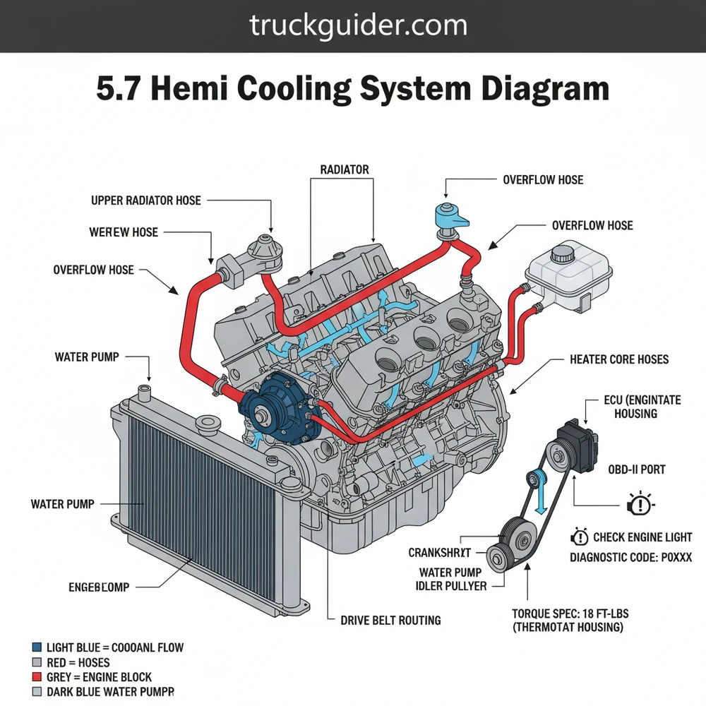
Understanding the 5.7 Hemi cooling system diagram is a fundamental requirement for any vehicle owner or technician looking to maintain the peak performance of this iconic engine. This guide provides a comprehensive breakdown of the pressurized liquid cooling circuit, identifying critical components ranging from the radiator and water pump to the intricate heater core lines. You will learn how to trace the path of coolant flow, interpret technical markings, and diagnose common failures using modern diagnostic tools. Whether you are performing a routine flush or a major water pump replacement, this detailed analysis ensures you have the technical clarity to keep your engine operating within its safe thermal window.
The 5.7 Hemi cooling system diagram serves as a roadmap for the thermal management of the engine block and cylinder heads. At the core of the diagram is the water pump, which is driven by the accessory belt. The diagram typically illustrates a “cross-flow” radiator design where the hot coolant enters through the upper radiator hose and exits through the lower hose after being cooled by airflow. You will notice the thermostat housing is positioned prominently near the top of the engine, acting as a gatekeeper that regulates flow based on engine temperature.
In most 5.7 Hemi configurations, the diagram will show a bypass circuit that allows coolant to circulate through the block and heater core even when the thermostat is closed. This is vital for engine warm-up and cabin heating. Color-coding in these diagrams often uses red or orange arrows to represent high-temperature “outflow” from the engine to the radiator, and blue or green arrows to represent “return” flow that has been cooled. Visualizing the expansion tank or “overflow bottle” is also crucial; the diagram indicates its role as a reservoir that manages fluid expansion and air bleeding. While various vehicle models—such as the Ram 1500, Charger, or Grand Cherokee—may have slightly different hose routing, the fundamental components of the 5.7 Hemi cooling system remain consistent across the platform.
[DIAGRAM PLACEHOLDER: 5.7 HEMI COOLING SYSTEM SCHEMATIC]
Visual Representation of: Radiator, Upper/Lower Hoses, Water Pump Assembly, Thermostat, Heater Core, Expansion Tank, and Temperature Sensors.
The 5.7 Hemi utilizes a 180°F to 203°F thermostat depending on the specific application. Using the incorrect temperature range can trigger a check engine light or prevent the ECU from entering “closed loop” fuel management mode.
To effectively use the 5.7 Hemi cooling system diagram for repairs or maintenance, follow this systematic guide to interpretation and application:
- Locate the Radiator and Pressure Cap: Start at the front of the diagram. The radiator is the primary heat exchanger. Identify the pressure cap, which maintains the system’s boiling point. Never open this cap when the engine is hot, as the pressurized coolant can cause severe burns.
- Identify the Upper and Lower Radiator Hoses: Trace the path from the top of the radiator to the engine (upper hose) and the bottom of the radiator to the water pump (lower hose). The lower hose is the “cold” side of the circuit, while the upper hose is the “hot” side.
- Find the Water Pump and Thermostat: The water pump is the central hub. On the 5.7 Hemi, it is located on the front of the engine block. The thermostat is usually housed in a bolt-on neck on the water pump or timing cover area. When replacing this, always ensure the air bleed notch (if present) is facing upward.
- Trace the Heater Core Lines: Look for two smaller hoses branching off towards the firewall. These supply hot coolant to the interior heating system. If you have no heat in the cabin but the engine is warm, these lines are the first place to check for blockages or air pockets.
- Map the Accessory Belt Path: Since the water pump is belt-driven, the cooling diagram is often overlaid with the accessory belt routing. Ensure the belt is properly tensioned and not glazed, as a slipping belt will lead to immediate overheating.
- Identify the ECT (Engine Coolant Temperature) Sensor: The ECU relies on this sensor to monitor heat. In the diagram, locate its position (usually near the thermostat) to understand how the computer gathers data to trigger the electric cooling fans.
- Verify the Expansion Tank Connection: Follow the small diameter hose from the radiator neck to the plastic reservoir. This tank allows for the natural expansion of coolant and provides a visual reference for fluid levels.
When installing a new water pump, strictly adhere to the manufacturer’s torque spec for the mounting bolts. Over-tightening can crack the timing chain cover, while under-tightening will lead to persistent leaks and potential engine failure.
Working on the 5.7 Hemi requires specific tools to ensure the job is done correctly. You will need a set of metric sockets (10mm, 13mm, and 15mm are common for this engine), a torque wrench, a coolant pressure tester, and an OBD-II scanner. The OBD-II scanner is particularly useful for verifying that the ECU is receiving accurate data after a repair.
Common issues with the 5.7 Hemi cooling system often manifest as a check engine light or a rising temperature gauge. One of the most frequent problems is a stuck thermostat. When this occurs, the ECU may
Another common point of failure is the water pump bearing or seal. If you notice a “chirping” sound from the front of the engine or see coolant weeping from the “weep hole” on the pump body, replacement is urgent. The diagram helps you identify that the water pump is situated near the timing chain cover. While they are separate systems, a massive water pump leak can sometimes contaminate the front crank seal area, making it vital to address leaks immediately.
If the vehicle is overheating at idle but cools down while driving, the diagram helps you focus on the electric cooling fans or a clogged radiator core. Conversely, if it overheats only at high speeds, you might be looking at a collapsing lower radiator hose or a restricted flow within the radiator. Using an OBD-II device to monitor “Live Data” allows you to see the exact numerical temperature the ECU is seeing, which is far more accurate than the dashboard needle.
When refilling the system, use a “no-spill” funnel or a vacuum-fill tool. The 5.7 Hemi is notorious for trapping air pockets in the heater core and upper cylinder heads, which can cause localized hotspots and “bubbling” sounds in the dash.
To maximize the lifespan of your cooling system, follow these best practices:
- ✓ Use the Correct Coolant Type: Most 5.7 Hemi engines require OAT (Organic Additive Technology) or HOAT (Hybrid Organic Additive Technology) coolant, depending on the production era. Mixing these can cause the fluid to turn into a “gel” that clogs the radiator.
- ✓ Inspect the Accessory Belt: Check for cracks every 30,000 miles. A broken belt stops the water pump instantly, leading to catastrophic overheating within minutes.
- ✓ Observe Torque Specs: For the water pump bolts, the common torque spec is approximately 18-22 ft-lbs (verify your specific service manual). Using a calibrated torque wrench prevents stripping the aluminum threads in the timing cover.
- ✓ Monitor Diagnostic Codes: Even if the gauge looks normal, if the check engine light appears, scan it immediately. Codes related to the cooling system are “Type A” codes that should never be ignored.
- ✓ Check Hose Integrity: Squeeze the radiator hoses when the engine is cool. They should feel firm but pliable. If they feel crunchy or overly soft, the internal structure has failed.
Maintaining the 5.7 Hemi involves understanding how the coolant flow interacts with the mechanical components of the engine. Because the water pump is located in such close proximity to the timing chain assembly, any work in this area should be done with cleanliness in mind to prevent debris from entering the engine. Furthermore, ensuring the ECU is reset after replacing a sensor or thermostat allows the computer to re-learn the engine’s thermal mapping, ensuring smoother operation.
In conclusion, the 5.7 Hemi cooling system diagram is more than just a picture; it is an essential diagnostic tool. By understanding the flow of coolant from the radiator through the water pump and block, and recognizing the role of the ECU and OBD-II diagnostics, you can ensure your engine remains healthy for years to come. Regular inspections, adherence to torque specifications, and using high-quality components are the keys to avoiding expensive repairs and maintaining the legendary performance of the Hemi engine. Whether you are a DIY enthusiast or a professional, keeping this schematic in mind during every service interval is the best way to prevent thermal stress and engine failure.
Step-by-Step Guide to Understanding the 5.7 Hemi Cooling System Diagram: Diagnosis & Fix Guide
Identify the primary components like the radiator, water pump, and thermostat housing on the 5.7 Hemi cooling system diagram.
Locate the coolant temperature sensor that communicates vital heat data to the vehicle ECU for engine management.
Understand how the coolant flows from the bottom radiator hose into the engine and exits through the thermostat.
Connect any replacement hoses or components, ensuring you follow the exact routing shown in the technical illustration.
Verify that all bolts are tightened to the manufacturer torque spec to prevent leaks under high pressure.
Complete the process by scanning the OBD-II port to clear any active check engine light or diagnostic code.
Frequently Asked Questions
Where is the thermostat located?
The thermostat is located at the front of the engine on the passenger side, housed within a neck where the upper radiator hose connects. This position allows it to regulate coolant flow directly into the block. Locating it accurately on the 5.7 Hemi cooling system diagram prevents confusion with other housing units.
What does the 5.7 Hemi cooling system diagram show?
This diagram shows the complete circulation path of coolant through the 5.7L V8 engine. It details the interaction between the radiator, water pump, heater core, and overflow reservoir. Following the flow helps technicians isolate whether a cooling issue is caused by a mechanical failure or a simple blockage.
How many hoses and connections are in the system?
The 5.7 Hemi cooling system typically features two main radiator hoses, two heater core hoses, and a bypass hose. Additionally, electrical connections for the coolant temperature sensor send data to the ECU. Verifying these connections ensures the engine maintains an optimal operating temperature without triggering a check engine light.
What are the symptoms of a bad cooling system?
A bad system often results in an illuminated check engine light and high temperature readings. You might experience coolant leaks near the water pump or hear gurgling sounds from the heater core. Scanning the OBD-II port for a diagnostic code like P0128 can confirm if the thermostat is stuck open.
Can I replace the water pump myself?
Yes, most owners can replace components like the thermostat or water pump using a 5.7 Hemi cooling system diagram. However, because the Hemi engine can be difficult to bleed, you must follow specific air-purging procedures to prevent air pockets. Always ensure the engine is completely cool before starting any work.
What tools do I need for cooling system repairs?
You will need a basic socket set, pliers for hose clamps, a drain pan, and a torque wrench to meet the specific torque spec for housing bolts. A vacuum bleed kit is also recommended for the 5.7 Hemi to ensure no air remains in the system after refilling the coolant.

![2014 Ram 3500 Transmission Guide: Full Specs & Data [2026]](https://truckguider.com/wp-content/uploads/2026/03/2014-ram-3500-transmission-featured.webp)
![Aisin vs. 68RFE: Specs & Fitment Guide [2026]](https://truckguider.com/wp-content/uploads/2026/03/aisin-transmission-ram-3500-featured.webp)
![Ram Extended Warranty Price [2026]](https://truckguider.com/wp-content/uploads/2026/03/featured-c324498f.webp)
![Lifted 3rd Gen Cummins [2026]](https://truckguider.com/wp-content/uploads/2026/03/lifted-3rd-gen-cummins-featured.webp)