46RE Shift Linkage Diagram: Complete Component Guide
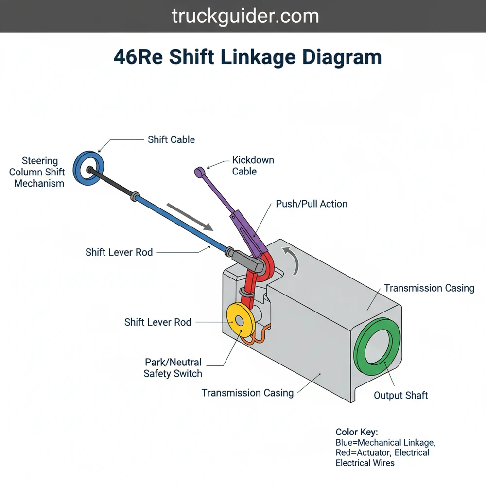
The 46RE shift linkage diagram illustrates the mechanical connection between the gear selector and the transmission lever. This system includes the shift cable, linkage arms, and bushings, ensuring precise gear engagement. Understanding this configuration is vital for troubleshooting gear misalignment or loose shifting issues in Chrysler vehicles.
📌 Key Takeaways
- Visualizes the connection between the gear selector and transmission manual lever
- Identifies critical bushings that commonly wear out over time
- Essential for adjusting the shift cable for proper gear alignment
- Shows the layout of the torque shaft and linkage rod assembly
- Used when the vehicle fails to engage Park or Neutral correctly
If you find yourself struggling to engage the correct gear or noticing a significant amount of “play” in your gear selector, obtaining a clear 46re shift linkage diagram is the first step toward a successful repair. The 46RE transmission, a staple in heavy-duty SUVs and trucks for years, relies on a series of mechanical connections to translate your physical movement of the gear shifter into the hydraulic and mechanical changes required within the transmission case. This comprehensive guide provides a deep dive into the 46re shift linkage diagram, offering a clear schematic of the system while explaining how each component functions within the broader transmission configuration. By understanding this blueprint, you can diagnose issues, replace worn parts, and ensure your vehicle shifts smoothly and safely.
Understanding the 46RE Shift Linkage Diagram and Component Layout
The 46re shift linkage diagram serves as a technical overview of how force is transferred from the driver’s hand to the transmission. Unlike modern drive-by-wire systems, the 46RE uses a robust, mechanical layout consisting of rods, pivots, and levers. When viewing a schematic of this system, you will typically see two primary configurations: the column-shift layout and the floor-shift layout. While the endpoints are similar, the routing of the rods varies significantly.
The core of the system is the control rod, which connects the steering column or floor shifter to the torque shaft. The torque shaft, sometimes referred to as a “Z-bar” due to its physical structure, acts as a fulcrum that changes the direction of the shifting force. This component is mounted between the frame of the vehicle and the transmission housing. Within the diagram, you will notice specific color-coding or numeric labeling used to identify the various bushings and grommets. These small plastic or rubber pieces are arguably the most critical elements in the assembly, as they prevent metal-on-metal contact and eliminate vibrations.
In a typical 46re shift linkage diagram, the following primary components are identified:
- ✓ Gearshift Control Rod: The main linkage piece that travels from the cabin to the underside of the vehicle.
- ✓ Torque Shaft Assembly: The central pivot point that bridges the gap between the engine/transmission block and the frame.
- ✓ Adjustable Swivel: A threaded block that allows for fine-tuning the length of the linkage to ensure gear synchronization.
- ✓ Transmission Shift Lever: The final arm that enters the transmission case to actuate the internal valve body.
- ✓ Grommets and Bushings: The sacrificial wear items located at every connection point in the blueprint.
Most 46RE linkage problems are not caused by the rods themselves but by the failure of the plastic grommets. When these grommets disintegrate, the rod gains excess clearance, leading to a “sloppy” shifter feel or the inability to reach Park or Low gears.
Comprehensive System Anatomy and Technical Structure
📤 Share
💾 Download
To properly interpret a 46re shift linkage diagram, one must understand the mechanical physics at play. The 46RE transmission is a four-speed automatic that uses a mechanical throttle valve (TV) cable alongside the gearshift linkage. While the TV cable controls shift timing and pressure, the shift linkage controls the actual gear selection (Park, Reverse, Neutral, Drive, 2, 1).
The structure of the linkage is designed to isolate the cabin from the natural torque-induced movement of the engine and transmission. Because the engine sits on rubber mounts, it moves slightly under load. The torque shaft (the Z-bar) in the linkage configuration is designed with a pivot on the frame and a pivot on the transmission. This allows the transmission to move up and down without accidentally pulling the vehicle out of gear. If you are looking at a blueprint of the system, you will see that the torque shaft has two distinct arms. One arm receives the “input” from the driver, and the other provides the “output” to the transmission.
In terms of material, the rods are generally made of heavy-gauge steel. The swivel assembly usually consists of a threaded rod and a locking bolt. This is the “adjustment point” that you will likely interact with most during a repair. If the blueprint shows a “swivel lock,” this is the specific bolt you loosen to realign the shifter with the internal detents of the transmission.
Step-by-Step Guide: Interpreting the Diagram and Adjusting the Linkage
📤 Share
💾 Download
Reading the 46re shift linkage diagram is one thing; applying that knowledge under the vehicle is another. Follow these steps to use the schematic for a full adjustment or component replacement.
Always perform linkage adjustments with the engine off and the wheels securely chocked. If the linkage is disconnected while the vehicle is on a slope, it can roll unexpectedly, even if the internal transmission is set to Park.
Step 1: Preparation and Tool Gathering
Before sliding under the vehicle, gather the necessary tools. You will typically need a 1/2-inch wrench or socket, a flat-head screwdriver (for prying out old bushings), a pair of pliers, and a high-quality silicone-based lubricant. Having the 46re shift linkage diagram printed out or available on a tablet will help you identify which rod goes into which hole on the torque shaft.
Step 2: Component Identification
Locate the torque shaft between the frame and the transmission. Compare what you see to the blueprint. Identify the control rod coming down from the steering column. Ensure that the rod is not bent or obstructed by exhaust heat shields or aftermarket headers.
Step 3: Neutral Alignment (The Calibration Phase)
To adjust the linkage accurately, most manufacturers recommend the “Neutral Method.” Have an assistant sit in the driver’s seat and move the gear selector to the “Neutral” position. Underneath the vehicle, locate the shift lever on the side of the transmission. Move it manually until you feel the distinct “click” of the Neutral detent.
Step 4: Loosening the Swivel Bolt
Referencing your 46re shift linkage diagram, find the swivel lock bolt on the adjustable rod. Loosen this bolt so the rod can slide freely within the swivel block. This effectively “unlinks” the cabin selector from the transmission lever while keeping them physically connected.
Step 5: Seating the Linkage
Ensure the shifter in the cabin is perfectly centered on the Neutral mark. Ensure the transmission lever is perfectly in the Neutral detent. With both sides synchronized, tighten the swivel lock bolt to the specified torque (usually around 100 inch-pounds).
Step 6: Testing the Range of Motion
Cycle the shifter through all gears: Park, Reverse, Neutral, Drive, 2, and 1. The shifter should move smoothly into each gate. Pay close attention to “Park” and “1.” If the linkage is too long, you may struggle to hit Park; if it is too short, you may not be able to reach the lowest gear.
Step 7: Bushing Replacement (If Necessary)
If the diagram indicates a bushing at a junction where you see a massive gap, you must replace the grommet. Use your pliers to press the new plastic bushing into the lever hole first, then use a lubricant to pop the metal rod through the center of the bushing.
If you are struggling to press in new bushings, soak them in a cup of hot water for five minutes. This softens the plastic, making it much easier to snap into the metal eyelets without cracking the new component.
Common Issues & Troubleshooting with the 46RE Linkage
Even with a perfect 46re shift linkage diagram, troubleshooting can be tricky. The most common symptom of a linkage issue is a “misalignment of the needle.” If your dash indicator says you are in Drive, but the car is actually in Neutral, the mechanical synchronization has drifted.
Another frequent problem is the “no-start” condition. The 46RE uses a Neutral Safety Switch (NSS) located on the transmission case. If the shift linkage is worn or misadjusted, the internal lever may not be fully engaging the “Park” or “Neutral” position on the switch. Even if your shifter looks like it is in Park, the transmission might be slightly off-center, preventing the starter from engaging.
Look for these warning signs:
- ✓ Excessive Vibration: Often caused by a missing torque shaft bushing, allowing the metal rod to rattle against the frame.
- ✓ Hard Shifting: If you have to “slam” the lever into Park, the linkage is likely too long or the rods are binding.
- ✓ Falling Out of Gear: A dangerous condition where the shifter moves but the transmission stays in the previous gear due to a disconnected rod.
If you inspect the system and find that the rods are severely rusted or the pivot points on the frame are cracked, it is time to seek professional help or order a complete linkage rebuild kit. Mechanical failure of the metal components is rare but can occur in high-mileage or off-road vehicles.
Maintenance Tips and Best Practices
To keep your transmission shifting correctly, maintenance should extend beyond just fluid changes. The external linkage system requires periodic attention to prevent the need for a total overhaul.
First, prioritize lubrication. Every six months, spray the pivot points identified in your 46re shift linkage diagram with a dry-film lubricant or a light lithium grease. Avoid using heavy greases that attract dirt and road salt, as this creates an abrasive paste that wears down the plastic bushings faster.
Second, consider upgrading your components. Many aftermarket companies offer “heavy-duty” bushing kits made of polyurethane rather than the standard soft plastic. These provide a much firmer shift feel and last significantly longer under high-heat conditions. Since the 46RE is often paired with V8 engines that generate substantial exhaust heat, these heat-resistant upgrades are a wise investment.
Third, keep an eye on the mounting brackets. The torque shaft is held to the transmission by a bracket. If the bolts on this bracket vibrate loose, the entire schematic falls out of alignment. Check these bolts for tightness whenever you are performing an oil change.
Finally, always use high-quality replacement parts. While it may be tempting to use a “universal” linkage kit, the 46RE has specific rod lengths and bends that are difficult to replicate with generic hardware. Sticking to the specifications found in a genuine 46re shift linkage diagram ensures that the geometry of the shift remains correct, preventing internal wear on the transmission’s manual valve.
When replacing bushings, check the condition of the metal “eyelets” on the rods. If the eyelets have become oval-shaped due to years of friction without a bushing, a new bushing will not sit securely. In this case, the rod itself must be replaced or repaired with a shim.
Concluding Thoughts on the 46RE Linkage System
Mastering the 46RE transmission’s shifting mechanics starts with a clear understanding of the 46re shift linkage diagram. Whether you are performing a routine adjustment to fix a loose gear selector or conducting a full restoration of the linkage assembly, the schematic serves as your roadmap. By identifying the key components—the torque shaft, control rods, and vital bushings—you can ensure that your vehicle remains reliable and responsive.
Proper alignment of the linkage not only improves the driving experience but also protects the internal components of the transmission from damage caused by partial gear engagement. Regular inspection, lubrication of pivot points, and the timely replacement of worn plastic grommets will keep your 46RE shifting smoothly for miles to come. Remember that a small investment in maintaining these mechanical connections can prevent the high cost of transmission repairs down the road. Keep your diagram handy, stay patient with the adjustment process, and you will find that the 46RE system is one of the most straightforward and rewarding mechanical systems to maintain on your vehicle.
Frequently Asked Questions
Where is the 46RE shift linkage located?
The 46RE shift linkage is located on the driver’s side of the transmission housing. It connects the gear selector, whether column-mounted or floor-mounted, to the manual lever on the side of the transmission case. You can typically see the external rods and pivots from underneath the vehicle.
What does the 46RE shift linkage diagram show?
The diagram shows the complete mechanical system, including the shift cable, linkage rods, grommets, and the torque shaft. It illustrates the structure and mounting points that allow driver input to physically move the transmission’s internal valve body to select Park, Reverse, Neutral, or Drive gears.
How many connections does the shift linkage system have?
The 46RE shift linkage system typically features three main connection points: the gear selector attachment, the frame-mounted torque shaft, and the manual lever on the transmission. Each point utilizes specialized bushings or clips to ensure the configuration remains stable and responds accurately to movements of the shifter.
What are the symptoms of a bad shift linkage?
Symptoms include a loose or ‘sloppy’ gear shifter, the needle not aligning with the gear indicators, or the vehicle failing to start because it cannot engage the neutral safety switch. You may also find it difficult to move the shifter into lower gears or into the Park position.
Can I replace the shift linkage components myself?
Yes, replacing linkage components is a common DIY task. Most repairs involve replacing worn plastic bushings or adjusting the shift cable length. Since the components are external to the transmission case, you do not need to open the transmission, making it a straightforward mechanical project for most owners.
What tools do I need for shift linkage repair?
You will need a standard socket set, a set of pliers, and a flat-head screwdriver for prying off old clips. A can of penetrating oil like PB Blaster is highly recommended for loosening rusted bolts on the torque shaft, and white lithium grease is useful for lubricating new bushings.

![RAM 1500 Tail Light Bulb Guide: Sizes & LED Upgrades [2026]](https://truckguider.com/wp-content/uploads/2026/03/ram-1500-tail-light-bulb-featured-768x403.webp)
![How Wide is a Ram 1500? Exact Dimensions & Mirror Specs [2026]](https://truckguider.com/wp-content/uploads/2026/03/how-wide-is-a-ram-1500-featured.webp)