Simple Dodge Alternator Wiring Diagram: Easy Setup Guide
A simple dodge alternator wiring diagram typically features a main output stud connected to the battery. External regulators connect via a field wire to the common terminal, while a ground wire ensures system stability. Understanding how the hot wire carries current to the battery is essential for a functional and safe charging system setup.
📌 Key Takeaways
- Visualizing the electrical flow between the battery, regulator, and alternator
- Identifying the main B+ output terminal for direct battery connection
- Ensuring a solid chassis ground to prevent dangerous voltage drops
- Using a digital multimeter to verify output after every installation
- Perfect for classic Dodge restorations or external regulator conversions
Understanding the electrical architecture of your vehicle is the first step toward a successful repair or upgrade. When you are dealing with a charging system failure, a simple dodge alternator wiring diagram serves as your primary roadmap for identifying connection points and ensuring the battery receives the necessary current. Dodge vehicles, particularly those using the Chrysler-style externally regulated or PCM-regulated systems, have a unique wiring logic compared to other manufacturers. By following a clear diagram, you can avoid the catastrophic mistake of crossing a field wire with a high-amperage output, which could lead to fried electronics or even an engine bay fire. In this guide, you will learn how to identify each terminal, understand the flow of electricity from the alternator to the battery, and master the specific color codes used in these classic and modern charging circuits.
Decoding the Simple Dodge Alternator Wiring Diagram
The core of any simple dodge alternator wiring diagram is the identification of three main connection points: the battery output, the field terminals, and the ground. Unlike modern “one-wire” alternators that have internal regulators, many Dodge systems utilize the Powertrain Control Module (PCM) or an external voltage regulator to manage how much electricity the alternator produces. This makes the wiring slightly more complex but much more precise for the vehicle’s needs.
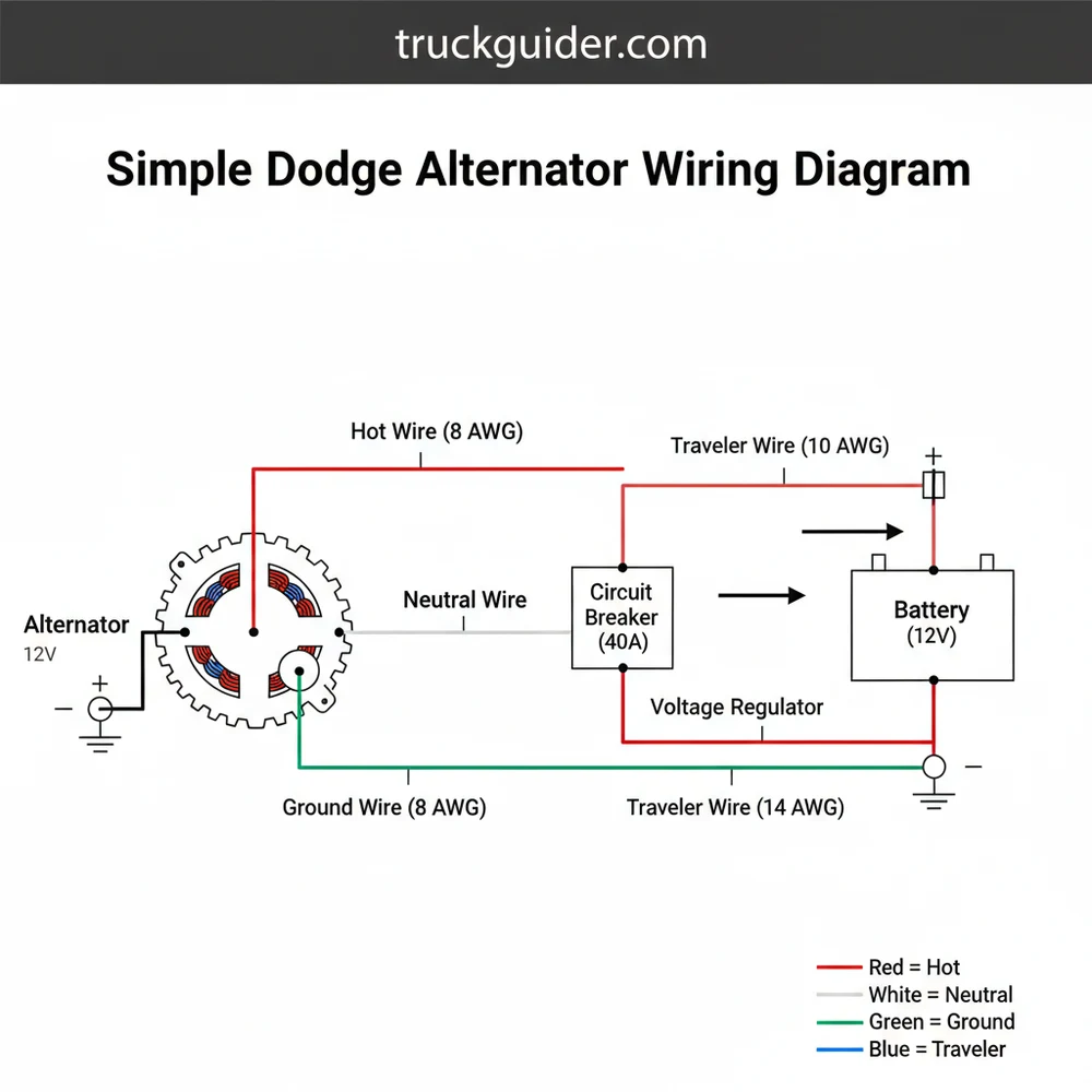
When looking at the diagram, the most prominent feature is the B+ terminal. This is often a large threaded stud, frequently featuring a brass screw or nut to ensure a high-conductivity connection. This is the hot wire of the charging system. It carries the full amperage output of the alternator directly to the positive terminal of the battery or through a heavy-duty fuse link. In a standard diagram, this wire is usually depicted as a thick red line to indicate its heavy gauge and constant live status when the engine is running.
The next critical components are the field terminals, often labeled F1 and F2. In a simple dodge alternator wiring diagram, these represent the “control” side of the system. One of these wires typically receives a 12-volt signal whenever the ignition is in the run position, while the other is pulsed to ground by the voltage regulator to control the magnetic field strength inside the alternator. This pulsed wire acts similarly to a traveler wire in residential three-way circuits, as it carries the fluctuating signal that dictates the system’s overall output.
On most Dodge vehicles, the alternator case itself serves as the primary ground. However, some heavy-duty or late-model versions include a dedicated ground wire terminal. Always ensure the mounting surfaces are clean and free of paint to maintain electrical continuity.
The visual representation above illustrates the flow from the battery to the alternator and back through the regulation circuit. Note the distinction between the high-current output path and the low-current regulation path. Understanding this distinction is vital because using the wrong wire gauge on the B+ terminal can cause excessive heat and voltage drop, rendering the charging system inefficient. Most diagrams will specify an 8-gauge or 6-gauge wire for the output, while the field wires usually require a much thinner 18-gauge or 16-gauge wire.
Step-by-Step Installation and Wiring Guide
📤 Share
💾 Download
Following a simple dodge alternator wiring diagram requires a methodical approach. Before you begin stripping wires or loosening bolts, you must prepare the vehicle to prevent accidental shorts. High-amperage DC systems are unforgiving, and even a brief touch of a hot wire to a grounded component can cause significant damage.
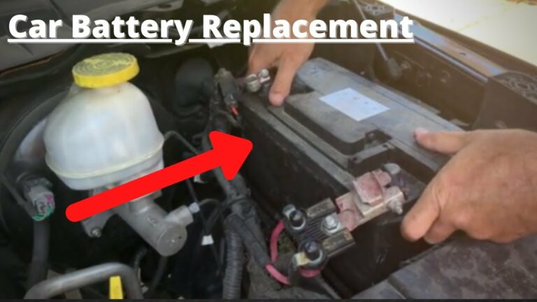
Always disconnect the negative battery cable before working on the alternator wiring. Failure to do so can result in an electrical arc that may damage the vehicle’s computer or cause personal injury.
- ✓ Step 1: Identify the Main Output Terminal – Locate the largest stud on the back of the alternator. This is the B+ or “hot” terminal. Connect the heavy-gauge red wire here. This wire typically leads directly to the battery or a starter relay. Ensure the nut is tightened securely against the brass screw or stud to prevent arcing.
- ✓ Step 2: Connect the Field Wires – Look for the two smaller terminals, usually marked with plastic insulators. On a Dodge, these are non-polarized in many older models, but in newer ones, they plug into a specific plastic connector. One wire provides the “excitation” voltage, while the other connects to the regulator. In some diagrams, the wire providing the constant 12V is referred to as the common terminal for the field circuit.
- ✓ Step 3: Establish the Ground Path – If your alternator has a dedicated ground stud (labeled ‘GND’ or ‘GRND’), connect a black ground wire from this stud to the engine block or the negative battery terminal. If there is no stud, ensure the alternator brackets are clean metal. This functions as the neutral wire equivalent in a DC system, providing the return path for the electrical current.
- ✓ Step 4: Verify Wire Gauges – Check your diagram for the specified gauge. Using a wire that is too thin for the main output will lead to a drop in voltage and could melt the insulation. Most Dodge diagrams recommend at least an 8-gauge wire for the main charging line.
- ✓ Step 5: Route Wires Safely – Use plastic looms and zip ties to keep the wires away from high-heat areas like the exhaust manifold and moving parts like the fan belt. A wire that rubs against the frame will eventually short out, causing the system to fail.
- ✓ Step 6: Final Terminal Inspection – Ensure all connections are tight. A loose connection at the alternator creates high resistance, which leads to heat and eventual terminal failure. Check that no stray wire strands are touching the alternator housing.
- ✓ Step 7: Reconnect and Test – Reconnect the negative battery terminal. Start the engine and use a multimeter to check the voltage at the battery. It should read between 13.8V and 14.4V if the wiring is correct and the regulator is functioning.
Use dielectric grease on the field terminal connections. This prevents corrosion and ensures a solid signal from the voltage regulator, which is especially important in the harsh environment of an engine bay.
Understanding Electrical Terminology in Automotive Context
📤 Share
💾 Download
While some terms like traveler wire or neutral wire are more common in household AC wiring, they have functional equivalents in a simple dodge alternator wiring diagram. In a DC automotive system, we focus on the “source” and “return” paths. The hot wire is always the one carrying current from the battery or alternator to the load. The ground wire serves as the return path, completing the circuit back to the battery’s negative post.
The field circuit in a Dodge alternator is a bit different. It uses two wires to create an electromagnetic field. In some technical manuals, one of these is referred to as the “sense” wire because it tells the regulator what the current system voltage is. If the regulator detects the voltage is too low, it increases the current through the field wires, which in turn causes the alternator to produce more power. This feedback loop is the heart of your vehicle’s charging system, and even one loose wire in this loop can result in a completely dead battery.
Common Issues and Troubleshooting the Wiring
Even with a perfect simple dodge alternator wiring diagram, problems can arise due to age, heat, and vibration. One of the most frequent issues is a “no-charge” condition where the alternator is spinning but the battery is draining. This is often traced back to the field circuit. If the excitation wire (the one that should have 12V when the key is on) is broken, the alternator will never “turn on.”
Another common problem is overcharging, where the voltage exceeds 15V. This is dangerous because it can boil the battery acid and blow out light bulbs. This usually indicates a short to ground in the field circuit or a failed voltage regulator. By using your diagram, you can probe the wires with a multimeter to see where the signal is being lost. Check the continuity between the field terminals and the regulator plug to ensure there isn’t a hidden break in the insulation.
Flickering headlights are another warning sign. This often suggests a poor ground connection. If the alternator cannot find a clean “neutral” path to complete its circuit, the voltage will fluctuate wildly. Cleaning the mounting bolts and the common terminal ground points often solves this without needing to replace any expensive parts.
Maintenance and Quality Components
To ensure your charging system remains reliable, it is essential to use high-quality components. When replacing wires, always use automotive-grade primary wire. Standard hardware store wire is not designed to withstand the heat, oil, and vibration found under a hood. Furthermore, when selecting an alternator, look for units with high-quality internal brushes and heavy-duty diodes.
Maintenance should include a periodic check of the belt tension. A slipping belt will prevent the alternator from reaching the RPMs required to produce full voltage, even if your wiring is perfect. Also, inspect the B+ terminal for signs of heat damage. If the plastic around the brass screw looks melted or discolored, it is a sign of high resistance and needs immediate attention.
Resistance is the enemy of any charging system. Every year, inspect your ground straps. A Dodge engine typically has multiple ground straps connecting the engine to the frame and the body. If these are corroded, your alternator cannot charge effectively.
Cost-saving advice often suggests “jumping” certain wires to test an alternator, but this is risky on Dodge vehicles with PCM-controlled regulators. If you bypass the regulator and apply full battery voltage to the field terminals (a process called full-fielding), do it only for a few seconds. Prolonged full-fielding can melt wires and damage the internal components of the alternator.
Optimizing Your Electrical System
For those running high-draw accessories like winches, off-road lights, or high-end audio systems, the standard wiring found in a simple dodge alternator wiring diagram might need an upgrade. This is often called the “Big Three” upgrade. It involves replacing the three most critical wires in the charging system with much larger 4-gauge or 0-gauge cables:
1. The wire from the alternator B+ terminal to the battery positive.
2. The ground wire from the battery negative to the engine block.
3. The ground wire from the engine block to the vehicle chassis.
By increasing the thickness of these paths, you reduce the resistance and allow the alternator to work much more efficiently. This ensures that even under heavy load, the voltage stays stable, protecting your sensitive electronics from brown-outs.
In conclusion, mastering the simple dodge alternator wiring diagram is an essential skill for any DIY mechanic or vehicle owner. By understanding the relationship between the hot wire, the field circuit, and the ground, you can diagnose charging issues with confidence. Always prioritize safety, use the correct wire gauge, and ensure every connection is tight and clean. With these principles in mind, your Dodge’s electrical system will remain robust and reliable for years to come, keeping your battery charged and your vehicle on the road.
Frequently Asked Questions
Where is the Dodge alternator located?
The alternator is usually found at the front of the engine, driven by the serpentine belt. On most Dodge vehicles, it is positioned on the upper passenger or driver side of the engine block, making it easily accessible for wiring inspections or replacement tasks.
What does this wiring diagram show?
This diagram illustrates the path of electrical current from the alternator to the battery. It specifically highlights the connections for the voltage regulator, the battery feed, and the ground, ensuring the vehicle’s electrical system receives a steady charge while the engine is running.
How many wires does a Dodge alternator have?
Most Dodge alternators feature a main B+ stud and two smaller field terminals. Unlike AC systems that require a neutral wire, automotive DC systems use the chassis as a return path. The diagram shows how these field wires connect to the common terminal for charging control.
What are the symptoms of a bad Dodge alternator?
Common symptoms include flickering headlights, a ‘Check Gauges’ warning, or a consistently dead battery. If you notice these issues, use the wiring diagram to check for loose connections, a blown fuse, or a faulty external voltage regulator before replacing the entire alternator unit.
Can I install a Dodge alternator myself?
Yes, replacing a Dodge alternator is a straightforward DIY task for most hobbyists. By following a wiring diagram, you can ensure that you do not cross the field wires and that the main battery cable is securely fastened to prevent arcing or electrical shorts.
What tools do I need for alternator wiring?
You will need a basic socket set to remove mounting bolts, a belt tensioner tool to release the drive belt, and a wire stripping tool if you are repairing connectors. A digital multimeter is also essential for verifying that the hot wire is delivering 13.5-14.5 volts.


![Hemi 5.7L V8 Multi Displacement Vvt Engineering [2026]](https://truckguider.com/wp-content/uploads/2026/03/featured-9ea6ee07-768x768.webp)
![2020 Ram 2500 Transmission: Specs & Fitment Guide [2026]](https://truckguider.com/wp-content/uploads/2026/03/2020-ram-2500-transmission-featured.webp)