Fuel Filler Neck Diagram: Quick Identification Guide
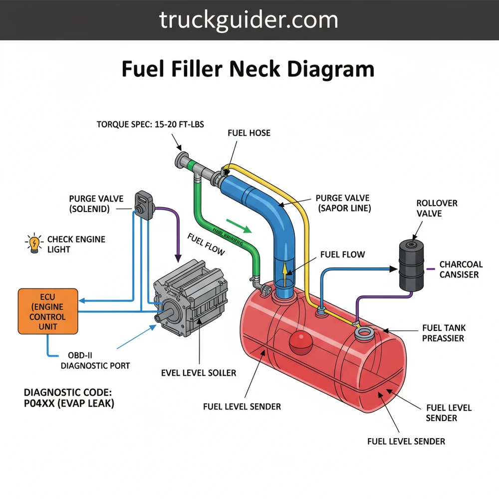
A fuel filler neck diagram illustrates the path from the gas cap to the fuel tank, including the metal tube, flexible hoses, and vent lines. It identifies critical seals and connections that, when leaking, trigger a diagnostic code via the ECU, helping you pinpoint the source of EVAP system failures.
📌 Key Takeaways
- Illustrates the physical connection between the fuel door and gas tank
- Identifies the main filler pipe and the auxiliary vent/breather lines
- Crucial for finding air leaks that cause emission system failures
- Shows location of mounting brackets and protective shields
- Used when replacing rusted pipes or troubleshooting gas station pump click-offs
Understanding the intricacies of your vehicle’s fuel delivery system is essential for both routine maintenance and troubleshooting complex performance issues. This guide provides a comprehensive fuel filler neck diagram overview, designed to help you identify every component from the fuel cap down to the fuel tank inlet. Whether you are dealing with a persistent check engine light or preparing for a complete component replacement, having a detailed visual and technical breakdown is your first step toward success. In the following sections, you will learn how the filler neck interacts with the vehicle’s emissions system, how to interpret technical schematics, and the precise steps required to ensure a leak-free installation. By the end of this article, you will possess a professional-level understanding of this critical automotive assembly.
Understanding the Fuel Filler Neck Diagram Components
A fuel filler neck diagram serves as a blueprint for the path fuel takes from the service station nozzle into your vehicle’s storage tank. While it may appear to be a simple metal or plastic tube, it is actually a sophisticated assembly of several interconnected parts designed to manage fluid flow, vapor pressure, and environmental safety. At the top of the diagram, you will find the filler neck housing and the fuel cap receiver. This area often includes a mounting flange that secures the neck to the vehicle’s body panels, usually behind the fuel door.
Moving down the assembly, the diagram typically highlights the primary filler tube and a secondary, smaller tube known as the vent or breather line. The primary tube is responsible for the high-volume flow of liquid fuel. The vent line, conversely, allows air and vapors to escape from the tank back toward the top of the neck as fuel enters, preventing the “back-splashing” or premature shut-off of the fuel nozzle. In many modern diagrams, you will also see a grounding strap or wire. This is a critical safety component designed to dissipate static electricity, preventing sparks during the refueling process.
The fuel filler neck is often constructed from galvanized steel to resist corrosion, but many newer vehicles utilize high-density polyethylene (HDPE) or composite materials to reduce weight and eliminate the risk of rust.
The lower portion of the diagram illustrates the connection point between the neck and the fuel tank. This is usually achieved through a heavy-duty rubber fuel hose secured by high-tension worm gear clamps or constant-tension spring clamps. Some specialized diagrams for high-performance or heavy-duty vehicles may also show an integrated “roll-over valve” located at the base of the neck, which prevents fuel from leaking out of the tank in the event of a vehicle inversion.
The Role of the EVAP System and the ECU
📤 Share
💾 Download
The fuel filler neck is a primary component of the Evaporative Emission (EVAP) system. This system is designed to trap fuel vapors before they escape into the atmosphere. The Electronic Control Unit (ECU) of your vehicle constantly monitors the pressure within this system. If the filler neck develops even a pinhole leak due to corrosion or a hairline crack, the ECU will detect a loss of vacuum or pressure during its self-test phase.
When the ECU identifies a discrepancy in the EVAP pressure, it triggers the check engine light on your dashboard. This is usually accompanied by a specific diagnostic code that can be retrieved via the OBD-II port. Understanding the relationship between the physical filler neck diagram and the digital signals sent to the ECU is vital for modern diagnostics. Unlike mechanical components like a timing chain or an accessory belt, which provide audible or physical symptoms of failure, a filler neck issue is often first identified by these electronic sensors.
Never ignore a check engine light related to the EVAP system. While the car may drive normally, a leaking filler neck can lead to increased fuel consumption, environmental damage, and potentially hazardous fuel odors near the rear of the vehicle.
How to Read and Interpret the Diagram for Installation
📤 Share
💾 Download
Reading a fuel filler neck diagram requires attention to detail regarding the orientation of the tubes and the placement of seals. When looking at a technical schematic, the “exploded view” is most common. This shows every bolt, washer, and clamp pulled away from the main body to show exactly where it fits. Before beginning any work, ensure you have gathered the necessary tools and prepared the work area.
- ✓ Socket set with extensions (typically 7mm to 13mm)
- ✓ Flathead and Phillips head screwdrivers
- ✓ Penetrating oil (for rusted mounting bolts)
- ✓ New fuel-grade rubber hose and clamps
- ✓ Safety glasses and fuel-resistant gloves
Step-by-Step Replacement Guide
1. Safety Preparation: Park the vehicle on a level surface and disconnect the negative battery terminal. This prevents any electrical sparks from occurring near the fuel system. Ensure the fuel tank is less than half full to minimize the risk of spillage.
2. Access the Filler Neck: Depending on your vehicle, you may need to remove the rear wheel on the side of the fuel door and the plastic inner fender liner. This will give you a clear view of the neck as it travels from the body to the tank.
3. Disconnect the Mounting Bolts: Locate the bolts securing the neck to the vehicle body (behind the fuel door). Use penetrating oil if they appear rusted. Refer to your diagram to ensure you have located all attachment points, including any mid-section brackets.
4. Loosen Hose Clamps: Slide under the vehicle to reach the connection at the fuel tank. Loosen the clamps on the flexible rubber hose. Be prepared for a small amount of residual fuel to leak out during this step.
5. Remove the Grounding Strap: If your vehicle is equipped with a grounding wire, carefully detach it from the chassis. This is often a small 10mm bolt that is highly susceptible to corrosion.
6. Extract the Old Neck: Carefully maneuver the old filler neck out of the vehicle. This may require some twisting and pulling, especially if the rubber hose has “fused” to the metal over time.
7. Install the New Assembly: Position the new filler neck according to the diagram. Slide the new rubber hose onto the fuel tank inlet first, then align the upper mounting flange with the holes in the body.
8. Final Tightening and Torque: Secure the mounting bolts and the grounding strap. Tighten the hose clamps firmly. While there is rarely a high torque spec for these small bolts, ensure they are “snug” to prevent vibration from loosening them later.
Apply a small amount of silicone-based lubricant to the inside of the new rubber hose. This makes it much easier to slide the hose over the fuel tank inlet and the new filler neck without tearing the rubber.
Common Issues and Troubleshooting
The most frequent problem associated with the fuel filler neck is corrosion. Because the neck is located in the wheel well, it is constantly bombarded by road salt, water, and debris. Over time, the metal can rust through, creating a “micro-leak” that triggers an OBD-II diagnostic code such as P0442 (Small Leak Detected) or P0455 (Large Leak Detected).
Another common issue is a blockage in the vent tube. If the vent tube is clogged by debris or a spider’s web (a surprisingly common occurrence), air cannot escape the tank as you refuel. This causes the fuel pump nozzle at the gas station to constantly click off, making a simple fill-up take much longer than it should. By consulting your fuel filler neck diagram, you can identify the vent tube and use compressed air to clear the obstruction.
Lastly, inspect the fuel cap gasket. A dried-out or cracked gasket on the cap is the leading cause of “false” filler neck concerns. Before replacing the entire neck assembly, always check that the cap is tightening correctly and that the seal is intact.
Maintenance and Best Practices
Maintaining your fuel filler neck is largely a matter of prevention and early detection. If you live in a region where road salt is used in the winter, make it a habit to spray the area behind the fuel door and inside the wheel well with fresh water during your car washes. This helps prevent the accumulation of salt that leads to rapid oxidation.
When purchasing replacement parts, always opt for OEM (Original Equipment Manufacturer) or high-quality aftermarket components. Inferior parts may not have the correct diameter for the vent tube, leading to fueling difficulties, or they may use lower-grade steel that will rust through in just a few seasons.
Additionally, consider the “holistic” health of your vehicle. While you are under the car inspecting the fuel lines, take a moment to look at other vital systems. Check your accessory belt for cracks or glazing, and observe the area around the water pump to ensure there is healthy coolant flow without leaks. Much like a timing chain requires proper lubrication and tension, your fuel system requires a sealed environment to operate within the parameters set by the ECU.
Modern ECU systems are extremely sensitive. Even leaving your gas cap one click too loose can store a diagnostic code. If your check engine light comes on shortly after refueling, always check the cap first.
Holistic Vehicle Health: Beyond the Filler Neck
While the fuel filler neck is the focus of this guide, it is part of a larger ecosystem. The fuel system relies on the engine’s mechanical timing and cooling efficiency to run at peak performance. For example, if your engine is running hot due to poor coolant flow, the fuel vapors in the tank may expand more rapidly, putting additional stress on the EVAP components and the filler neck seals.
Similarly, the electrical load required to run the fuel pump and the various sensors monitored by the ECU is supported by the alternator, which is driven by the accessory belt. If that belt is slipping, your electrical system may experience voltage drops that lead to “ghost” diagnostic codes in the EVAP system. Even the internal synchronization of the engine, managed by the timing chain, affects the vacuum pressure in the intake manifold, which is often used to purge fuel vapors from the charcoal canister. By maintaining a comprehensive view of your vehicle’s systems, you can distinguish between a localized mechanical failure and a systemic issue.
Conclusion
Navigating a fuel filler neck diagram is a vital skill for any DIY mechanic or vehicle owner looking to save money on repairs. By understanding the anatomy of the neck, from the mounting flange to the vent tube, you can effectively diagnose issues like fuel odors, difficult refueling, and stubborn check engine lights. Remember to utilize OBD-II scanners to pinpoint diagnostic codes early, and always follow safety protocols when working with the fuel system. With the right tools, a clear diagram, and the steps outlined in this guide, you can ensure your vehicle’s fuel delivery and emissions systems remain in top condition for miles to come. Proper maintenance of the filler neck not only keeps your vehicle running efficiently but also ensures that you pass emissions tests and contribute to a cleaner environment.
Frequently Asked Questions
Where is the fuel filler neck located?
The fuel filler neck is located behind the fuel filler door on the rear exterior panel of the vehicle. It extends downward from the fuel cap area, through the wheel well or body frame, and connects directly to the side or top of the fuel tank via heavy-duty rubber hoses.
What does fuel filler neck diagram show?
The diagram shows the assembly of the fuel intake system, including the metal neck, the gas cap housing, the breather tube, and the rubber connectors. It highlights how these components route fuel safely into the tank while managing vapor pressure through integrated vent lines and check valves within the system.
How many connections does fuel filler neck have?
Most fuel filler necks have three primary connections: the top opening for the gas cap, the main bottom outlet that joins the gas tank via a large rubber hose, and a smaller secondary vent line port. Some modern systems may include additional ports for the EVAP canister or pressure sensors.
What are the symptoms of a bad fuel filler neck?
Common symptoms include a persistent smell of gasoline around the rear of the vehicle or a check engine light on the dashboard. Using an OBD-II scanner often reveals a diagnostic code related to the EVAP system, such as P0442 or P0455, indicating a leak in the neck or cap.
Can I replace the fuel filler neck myself?
Yes, a fuel filler neck replacement is a common DIY task for those with basic tools. However, you must work in a well-ventilated area because of gasoline fumes. It usually involves removing the rear wheel, loosening hose clamps, and unbolting the neck from the vehicle body and fuel tank.
What tools do I need for fuel filler neck replacement?
You will need a floor jack, jack stands, a basic socket set, and screwdrivers for hose clamps. A torque wrench is highly recommended to ensure all mounting hardware meets the manufacturer torque spec. Additionally, having a penetrating lubricant like WD-40 helps loosen rusted bolts on older vehicle models.


![Ram 1500 Bed Rack with Tonneau Cover: Compatibility Guide [2026]](https://truckguider.com/wp-content/uploads/2026/03/ram-1500-bed-rack-with-tonneau-cover-featured.webp)