Dodge 318 Engine Diagram: Complete Identification Guide
A Dodge 318 engine diagram illustrates the layout of the 5.2L V8 power plant, detailing the intake manifold, cylinder heads, and accessory drive. It provides a visual map for locating critical components like the ECU and sensors, which is essential for diagnosing a check engine light or performing a full rebuild.
📌 Key Takeaways
- Visualize the internal and external component layout of the 5.2L V8 engine.
- Easily identify the intake manifold, distributor, and sensor positioning.
- Always verify the specific torque spec for head and intake bolts during assembly.
- Use the diagram alongside an OBD-II scanner for accurate sensor troubleshooting.
- Perfect for timing chain replacements, gasket repairs, or full engine overhauls.
Finding a reliable Dodge 318 engine diagram is the essential first step for any enthusiast or mechanic looking to maintain, repair, or restore this legendary Mopar power plant. Whether you are working on a classic LA block from the 1970s or a later Magnum series 5.2L V8, having a visual map of the engine components ensures accuracy and safety. This guide provides a comprehensive breakdown of the internal and external systems, covering everything from firing orders to sensor locations. By understanding how to read these diagrams, you will gain the confidence to tackle complex repairs, optimize performance, and keep your vehicle running smoothly for years to come.
Understanding the Dodge 318 Engine Diagram Layout
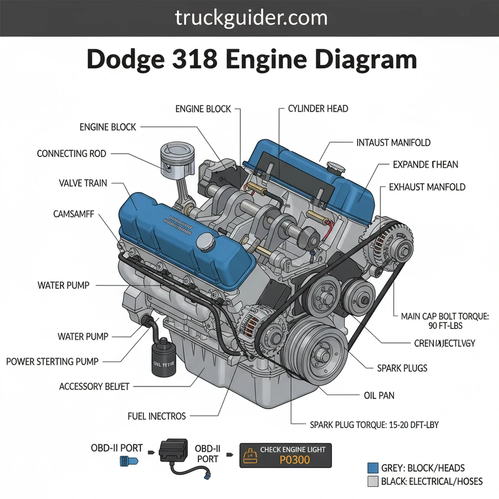
The Dodge 318 engine, known formally as the 5.2L V8, has evolved significantly over its production lifespan. A comprehensive dodge 318 engine diagram typically illustrates the small-block architecture, which is characterized by its compact design and 90-degree V-angle. To read the diagram effectively, you must first identify the orientation. Most diagrams view the engine from the front (the side with the accessory belt) or from a top-down perspective to show the intake manifold and cylinder arrangement.
In a standard diagram, the key components are grouped by system. The cooling system section will highlight the water pump, thermostat housing, and the complex path of the coolant flow through the block and heads. The ignition section identifies the distributor location (on older models) or the coil-on-plug arrangement on modern versions, alongside the firing order. On later Magnum engines, the diagram will also feature the fuel injection rail and various electrical connectors that interface with the ECU.
Color-coding is often utilized in high-quality diagrams to differentiate between fluid types. Blue lines typically represent the coolant flow, while red or orange lines might indicate high-temperature exhaust paths or oil galleries. Electrical schematics within the diagram use standardized symbols to show the path from the battery to the starter motor and the alternator. Understanding these visual cues is vital for identifying where a specific vacuum leak might be occurring or where a diagnostic sensor is hidden behind the intake plenum.
[DIAGRAM_PLACEHOLDER: A detailed exploded view of a Dodge 318 V8 engine showing the cylinder block, heads, intake manifold, accessory drive, and front timing cover.]
The diagram also serves as a guide for the physical layout of the cylinders. On the Dodge 318, the driver’s side bank contains cylinders 1, 3, 5, and 7, while the passenger’s side bank contains 2, 4, 6, and 8. This numbering is crucial when you are troubleshooting a specific diagnostic code related to a misfire. Without the diagram, it is easy to confuse the cylinder positions, leading to incorrect parts replacement or faulty wiring.
The Dodge 318 transition from the “LA” series to the “Magnum” series in the early 1990s introduced major changes, including bolt-down rockers and a different intake manifold bolt angle. Always ensure your diagram matches the specific era of your engine to avoid using the wrong torque spec during assembly.
Step-by-Step Guide: Interpreting and Using the Diagram

Using a dodge 318 engine diagram effectively requires a systematic approach. Whether you are performing a simple belt swap or a full top-end rebuild, follow these steps to ensure you are utilizing the technical data correctly.
Step 1: Identify the Engine Generation
Before turning a wrench, determine if you have an LA block (identified by the V-shaped valve covers with two bolts) or a Magnum block (identified by the vertical valve cover bolts and the presence of a serpentine accessory belt). The diagrams for these two versions differ significantly in terms of the timing chain cover and the oiling system.
Step 2: Locate the Firing Order and Cylinder Numbering
Refer to the diagram to locate cylinder number one (typically the front-most cylinder on the driver’s side). The firing order for the 318 is 1-8-4-3-6-5-7-2. If you are replacing spark plug wires, trace each line on the diagram from the distributor cap to the corresponding spark plug to prevent cross-firing.
Step 3: Trace the Accessory Belt Routing
One of the most frequent uses for a diagram is checking the accessory belt path. On Magnum engines, the serpentine belt follows a specific “S” pattern around the alternator, power steering pump, air conditioning compressor, and water pump. If the belt is routed incorrectly, the water pump may spin backwards, causing immediate overheating issues.
Step 4: Verify the Coolant Flow Path
Identify the “in” and “out” ports for the heater core and the radiator on your diagram. The Dodge 318 utilizes a bypass hose near the thermostat housing. Ensuring this hose is in good condition is critical for proper coolant flow during the engine’s warm-up phase.
Step 5: Reference Torque Specs for Major Bolts
A technical diagram often includes a table for the torque spec of critical fasteners. For the 318, the cylinder head bolts generally require 85-105 ft-lbs, while the intake manifold requires a much lower 25-45 ft-lbs (depending on the year). Using the diagram’s tightening sequence prevents warping the aluminum or cast-iron components.
Step 6: Identify Sensor Locations for Diagnostic Troubleshooting
If your check engine light is on, use the diagram to find the Oxygen (O2) sensors, the Manifold Absolute Pressure (MAP) sensor, and the Crankshaft Position Sensor. The latter is often tucked away at the back of the block near the transmission bellhousing, making it difficult to find without a visual aid.
Never attempt to remove the timing chain cover or intake manifold while the engine is hot. Always disconnect the battery before working near the alternator or starter motor to prevent electrical shorts and potential injury.
Essential Tools for Diagram-Based Repairs:
- ✓ Quality Torque Wrench (in-lb and ft-lb scales)
- ✓ OBD-II Scanner (for Magnum engines)
- ✓ Set of Feeler Gauges (for checking spark plug gaps)
- ✓ Serpentine Belt Tool or long Breaker Bar
- ✓ Multimeter for testing electrical continuity in the ECU harness
Common Issues and Troubleshooting with the 318
📤 Share
💾 Download
The Dodge 318 is a robust engine, but like any mechanical system, it has its weak points. Utilizing a dodge 318 engine diagram can help you pinpoint the source of common problems quickly. One frequent issue is the failure of the plenum gasket under the intake manifold on Magnum engines. This causes oil consumption and a rough idle. By looking at the diagram, you can see how the intake manifold is two pieces; a vacuum leak in this area often triggers a “lean” diagnostic code.
Another common problem involves the timing chain. Over time, the chain can stretch, leading to retarded ignition timing and poor performance. The diagram shows the relationship between the crankshaft gear and the camshaft gear. If the “dots” on these gears do not align according to the diagram, your engine’s internal timing is off, which could eventually lead to valve damage.
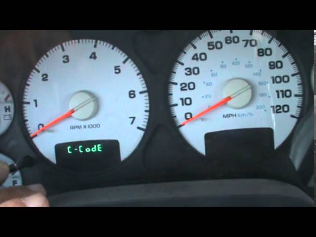
When the check engine light illuminates, it is usually tied to a sensor failure. For example, a faulty Coolant Temperature Sensor (CTS) can tell the ECU that the engine is cold when it is actually hot, leading to an over-rich fuel mixture. The diagram helps you locate this sensor near the thermostat housing so you can test it with a multimeter.
If you are experiencing a “No Start” condition on a Magnum 318, check the Crankshaft Position Sensor first. This sensor is a frequent failure point and its location at the back of the engine makes it hard to see, but the diagram will show you exactly where to reach.
Maintenance Best Practices and ECU Integration
To keep your Dodge 318 in peak condition, regular maintenance is required. On 1996 and newer models, the engine is fully integrated with an OBD-II system. This means the ECU (Engine Control Unit) constantly monitors inputs from various sensors identified in your diagram. If the ECU detects a parameter outside of the normal range, it will store a diagnostic code and trigger the check engine light.
Maintaining the accessory belt is one of the easiest ways to prevent a breakdown. Inspect the belt for cracks or fraying every 10,000 miles. Referencing your diagram ensures that if you do need to replace it, you won’t be left guessing how it fits back onto the pulleys. Additionally, pay close attention to the cooling system. The 318 is sensitive to heat; ensuring the coolant flow is unobstructed and the radiator is clean can prevent the heads from cracking.
When replacing components, always opt for high-quality gaskets and sensors. The Dodge 318 responds best to OEM-spec parts, particularly when it comes to the ECU-controlled sensors. Cheap aftermarket sensors can often provide “noisy” data signals, leading to erratic engine behavior and persistent diagnostic codes that are difficult to clear.
Technical Specifications and Firing Details
For those performing a deep dive into the engine, technical specifications are just as important as the visual dodge 318 engine diagram. Understanding the “numbers” behind the lines and labels is what separates a novice from an expert.
Engine Specifications:
- Displacement: 318 Cubic Inches (5.2 Liters)
- Cylinder Bore: 3.91 inches
- Stroke: 3.31 inches
- Compression Ratio: Usually between 8.5:1 and 9.1:1 depending on the year
- Spark Plug Gap: 0.035″ (LA) or 0.040″ (Magnum)
- Oil Pressure: 45-65 psi at 2000 RPM
The timing chain is the heartbeat of this engine. While the 318 is not an interference engine (meaning the valves won’t hit the pistons if the chain breaks), a failed chain will leave you stranded. Most diagrams will show the “Timing Marks” as two dots that must face each other at the closest point when cylinder #1 is at Top Dead Center (TDC).
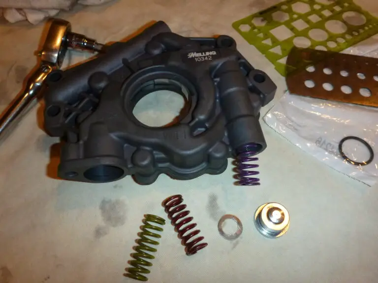
Furthermore, the oiling system on the 318 is a “priority main” system, which means the oil goes to the main bearings first before heading to the top end. If your diagram shows low oil pressure at the top end (valvetrain noise), the issue often lies in the cam bearings or a clogged oil pump pickup screen, both of which are central components in any detailed internal engine schematic.
Summary of the Dodge 318 Engine Diagram Benefits
In conclusion, having access to a high-quality dodge 318 engine diagram is a game-changer for anyone working on this classic Mopar V8. From identifying the correct path for the accessory belt to understanding the complexities of the ECU and OBD-II systems, the diagram provides the roadmap necessary for success. It allows you to troubleshoot a check engine light by locating sensors accurately and ensures that every torque spec is met during reassembly.
By following the step-by-step interpretation guide and adhering to the maintenance best practices outlined here, you can tackle everything from a simple coolant flow check to a complete timing chain replacement. The Dodge 318 is a testament to durable American engineering; with the right information and a bit of patience, you can ensure it continues to provide reliable power for many miles to come. Remember to always reference your diagram before starting a project, keep your tools organized, and never overlook the small details that make these engines legendary.
Frequently Asked Questions
Where is the ECU located on a Dodge 318?
The engine control unit or ECU is typically mounted on the passenger side firewall inside the engine bay. This location allows it to manage fuel injection and ignition timing. Locating it via the diagram is crucial when you need to test wiring harnesses or replace the unit entirely for repair.
What does the Dodge 318 engine diagram show?
This diagram provides a comprehensive visual breakdown of the 5.2L V8 engine. It highlights the location of the intake manifold, cylinder heads, water pump, and electronic sensors. It is designed to help owners visualize how mechanical parts and electrical systems interact for better maintenance and professional repair work.
What are the torque specs for the 318 intake manifold?
For a Dodge 318, the intake manifold torque spec is generally 35 ft-lbs, followed in a specific sequence to prevent vacuum leaks. Cylinder head bolts usually require 85-105 ft-lbs depending on the bolt type. Always consult the diagram to ensure you are tightening fasteners in the correct order.
What are the symptoms of a bad 318 engine sensor?
If your check engine light illuminates, it indicates that the ECU has detected a fault. By using the diagram to find sensors like the O2 or MAP sensor, you can inspect for physical damage before using an OBD-II scanner to pull a specific diagnostic code for further troubleshooting.
Can I replace the water pump myself?
Replacing a water pump or alternator on a 318 is a very manageable DIY task for most owners. The engine layout is relatively simple and spacious compared to modern vehicles. By following the diagram to understand belt routing and bolt locations, you can complete these repairs in a few hours.
What tools do I need for Dodge 318 diagnostics?
For most 318 engine work, you will need a standard socket set, torque wrench, and screwdrivers. If you are dealing with electronic issues, an OBD-II scanner is vital for reading a diagnostic code. The diagram will guide you on where to apply these tools for the best results.


![Lifted 3rd Gen Cummins [2026]](https://truckguider.com/wp-content/uploads/2026/03/lifted-3rd-gen-cummins-featured.webp)