5.2 Magnum Engine Diagram: Complete Identification Guide
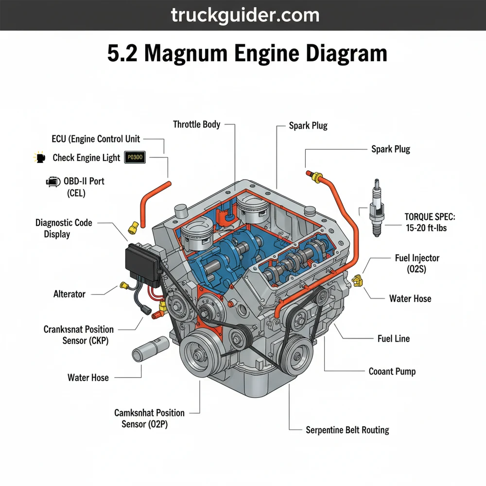
A 5.2 magnum engine diagram provides a visual layout of the V8’s core components, including the intake plenum, distributor, and sensor positions. It illustrates the routing for vacuum lines and electrical connections to the ECU, helping owners identify part locations for maintenance, troubleshooting, and performance upgrades on Dodge and Jeep vehicles.
📌 Key Takeaways
- Provides exact placement of sensors and mechanical parts
- Highlights the ECU as the central control hub for performance
- Essential for identifying common vacuum leak locations
- Assists in tracing electrical paths for wiring repairs
- Used primarily for diagnostic work and engine rebuilds
Whether you are performing a routine tune-up on a classic Dodge Ram or deep-diving into a complete rebuild of a Jeep Grand Cherokee, having a clear and accurate 5.2 magnum engine diagram is the single most important tool in your arsenal. This legendary small-block V8, often referred to as the 318 Magnum, is celebrated for its durability and relatively simple overhead valve (OHV) design. However, the complexity of its vacuum lines, sensor placements, and specific accessory belt routing can quickly become overwhelming without a visual reference. In this guide, you will learn how to identify every critical component of the engine, understand the flow of its cooling and electrical systems, and gain the technical confidence to troubleshoot common issues using diagnostic codes and physical inspections.
Understanding the 5.2 Magnum Engine Diagram Layout
The 5.2 Magnum engine serves as a bridge between old-school mechanical engineering and modern electronic management. When looking at a 5.2 magnum engine diagram, the first thing you will notice is the distinct “Kegler” intake manifold, named for its barrel-like shape, which sits prominently atop the engine block. This intake is central to the engine’s performance but is also a primary point of interest for maintenance. The diagram typically splits the engine into three main zones: the front-facing accessory drive, the top-mounted fuel and air delivery system, and the rear-mounted ignition distribution.
In the front of the diagram, you will find the accessory belt path. The 5.2 Magnum utilizes a serpentine belt system that powers the alternator, power steering pump, air conditioning compressor, and the water pump. Understanding this routing is essential because a single misplaced pulley can lead to belt slippage or premature wear. Below the belt system lies the timing chain cover, which hides the mechanical link between the crankshaft and the camshaft.
The electrical portion of the diagram highlights the transition to the OBD-II system found in later models. This includes the placement of the ECU (Engine Control Unit), which acts as the brain of the vehicle. The diagram will show wires leading from the ECU to various sensors like the Throttle Position Sensor (TPS), the Idle Air Control (IAC) motor, and the Manifold Absolute Pressure (MAP) sensor. Identifying these locations is vital when you are faced with a check engine light and need to pinpoint which component is failing.
The 5.2 Magnum uses a firing order of 1-8-4-3-6-5-7-2. When using the engine diagram to replace spark plug wires, ensure the wires are routed through the factory looms to prevent electromagnetic interference, which can cause phantom misfires and trigger a diagnostic code.
Step-by-Step Guide: How to Read and Apply the Diagram
📤 Share
💾 Download
Interpreting an automotive diagram requires a systematic approach. It is not just about looking at the pictures; it is about understanding the relationship between mechanical movement and electronic signals. Follow these steps to effectively use your 5.2 magnum engine diagram for repairs.
- Identify Your Orientation: Most diagrams are drawn from the perspective of someone standing at the front bumper looking toward the windshield. In this view, the “Driver’s Side” (Left) contains cylinders 2, 4, 6, and 8, while the “Passenger’s Side” (Right) contains cylinders 1, 3, 5, and 7.
- Locate the ECU and Sensor Hub: Before touching any mechanical parts, locate the ECU on your diagram. Trace the wiring harness to the sensors on the throttle body. This is the most common area for electrical troubleshooting when a check engine light appears. Use the diagram to identify the color-coding of the wires if you are performing a continuity test.
- Trace the Accessory Belt Routing: If you are replacing the water pump or alternator, refer to the accessory belt sub-section of the diagram. Note the position of the automatic tensioner. You will need a long-handled wrench or a breaker bar to release the tension. Ensure the belt ribs align perfectly with the grooves on the pulleys as shown in the visual guide.
- Verify Coolant Flow Path: The coolant flow in the 5.2 Magnum moves from the lower radiator hose, through the water pump, into the engine block, up through the cylinder heads, and out through the thermostat housing into the upper radiator hose. Use the diagram to locate the bypass hose—a small 90-degree hose that is a frequent leak point.
- Check the Ignition System: Follow the diagram from the ignition coil to the distributor cap located at the very back of the engine. Because the distributor is tucked under the cowl, the diagram is often the only way to see which terminal on the cap corresponds to which spark plug.
- Apply Torque Specifications: Once parts are identified and placed, use a technical chart to find the correct torque spec for each bolt. For example, the intake manifold bolts require a specific sequence and torque (typically 12 ft-lbs in multiple steps) to prevent the common plenum gasket failure.
Always disconnect the negative battery terminal before using the diagram to probe electrical connectors or work near the ECU. A short circuit can fry the computer, leading to an expensive replacement and complex re-programming.
Technical Specifications and Component Deep Dive
📤 Share
💾 Download
To fully utilize a 5.2 magnum engine diagram, you must understand the technical specifications that govern these components. The Magnum series was a significant upgrade over the older LA-series engines, featuring better-flowing heads and a more efficient fuel injection system.
The Fuel and Air System: The 5.2 uses Multi-Port Fuel Injection (MPFI). The diagram will show eight individual injectors located on the intake runners. These are managed by the ECU based on data from the O2 sensors and the MAP sensor. If your vehicle is struggling with a rough idle, the diagram helps you locate the IAC (Idle Air Control) valve, which is often clogged with carbon deposits.
The Timing System: Unlike modern engines with overhead cams and long belts, the 5.2 Magnum uses a short, robust timing chain. While very durable, the chain can stretch over hundreds of thousands of miles. The diagram illustrates how the timing marks on the crank sprocket and cam sprocket must align (usually at the 6 o’clock and 12 o’clock positions respectively) to ensure the engine is in time.
Cooling System Dynamics: The coolant flow is pressurized and regulated by a thermostat, usually rated at 195 degrees Fahrenheit from the factory. The diagram identifies the heater core supply and return lines. If you experience a lack of heat in the cabin, the diagram helps you trace these lines to check for blockages or trapped air.
- ✓ Displacement: 318 cubic inches (5.2 Liters)
- ✓ Cylinder Head Torque Spec: 105 ft-lbs (final step)
- ✓ Oil Capacity: 5 Quarts with filter
- ✓ Compression Ratio: 9.1:1
Common Issues and Troubleshooting with the Diagram
The 5.2 Magnum is a “workhorse,” but it has specific quirks that can be solved quickly if you know where to look on the 5.2 magnum engine diagram.
1. The Infamous Plenum Gasket Leak: This is the most common issue. The bottom plate of the intake manifold is made of steel, while the manifold itself is aluminum. Different expansion rates cause the gasket to blow out. Using your diagram, look for the belly pan of the intake. Symptoms include high oil consumption, spark knock (pinging), and a specific diagnostic code indicating a lean condition or misfire.
2. Crankshaft Position Sensor (CPS) Failure: This sensor is located on the passenger side bellhousing of the transmission. It is notoriously difficult to see, but the diagram shows its exact mounting point. When this sensor fails, the engine will crank but not start, or it may die suddenly while driving. The diagram is essential here because you often have to reach the sensor by feel.
3. OBD-II and the Check Engine Light: In 1996 and newer models, the ECU is highly sensitive. If the check engine light flashes, it often indicates a “catalyst damaging misfire.” By using the diagram to locate the O2 sensors (upstream and downstream), you can determine if the issue is a fuel-air mixture problem or a failing catalytic converter.
If you are getting a diagnostic code for a TPS or MAP sensor, don’t just replace the sensor. Use your diagram to check the vacuum lines first. A small crack in a 30-cent rubber hose can mimic the symptoms of a failed 50-dollar sensor.
Tips and Best Practices for Long-Term Maintenance
Owning a vehicle with a 5.2 Magnum means you have an engine capable of 300,000 miles if treated correctly. Maintenance should always be proactive rather than reactive.
Grounding and Electrical Health: The ECU on these engines is very sensitive to voltage fluctuations. Use your engine diagram to find all the ground straps—usually one from the battery to the block, and one from the block to the firewall. Ensure these connections are clean and free of corrosion. Poor grounding is a leading cause of erratic sensor readings and “ghost” diagnostic codes.
Cooling System Upgrades: Since the 5.2 Magnum generates significant heat, keeping the coolant flow optimal is critical. Many owners choose to replace the factory plastic-tank radiator with an all-aluminum unit. When doing this, refer to the diagram to ensure you don’t swap the heater hoses, which can lead to poor climate control performance.
Upgraded Ignition Components: The factory ignition system is adequate, but using the diagram to install a high-output coil and 8mm spark plug wires can improve fuel economy and throttle response. When rerouting wires, follow the diagram’s pathing strictly. The Magnum engine is susceptible to “cross-fire” if the wires for cylinders 5 and 7 are run too close and parallel to each other.
Cost-Saving Advice: Before taking your vehicle to a mechanic for a check engine light, buy a basic OBD-II scanner. Use the scanner to pull the diagnostic code, then refer to your 5.2 magnum engine diagram to locate the offending part. Doing the labor yourself on sensors like the IAC or TPS can save you hundreds of dollars in shop fees, as these are typically “plug-and-play” components that require only basic hand tools.
In conclusion, the 5.2 magnum engine diagram is more than just a map of parts; it is a comprehensive guide to the health and longevity of your vehicle. By understanding the accessory belt routing, the nuances of the ECU and OBD-II systems, and the specific torque spec requirements for internal components, you transition from a casual owner to a knowledgeable mechanic. Whether you are fixing a leak in the coolant flow or investigating a mysterious check engine light, this technical knowledge ensures your Magnum V8 continues to provide the power and reliability it was designed for. Consistent maintenance, guided by accurate diagrams, is the key to keeping these classic engines on the road for decades to come.
Frequently Asked Questions
Where is the ECU located?
The ECU, or Engine Control Unit, is typically found on the passenger side firewall or near the coolant overflow reservoir. By using the 5.2 magnum engine diagram, you can trace the main wiring harness from the engine sensors back to this module to troubleshoot signal or power delivery issues.
What does this 5.2 magnum engine diagram show?
The diagram displays the physical arrangement of the V8 engine block, including the intake manifold, fuel rail, and ignition system. It maps out the vacuum hose routing and the location of critical sensors, providing a clear roadmap for anyone performing mechanical repairs or electrical diagnostic work on the vehicle.
How many vacuum connections does the plenum have?
The 5.2 Magnum plenum generally features several vacuum connections serving the brake booster, PCV valve, and MAP sensor. The diagram specifies each port’s location, which is vital because incorrect routing can lead to vacuum leaks, causing a rough idle or triggering a frustrating check engine light on your dashboard.
What are the symptoms of a bad plenum gasket?
Common symptoms include excessive oil consumption, engine pinging, and a loss of power. When this gasket fails, it often causes the ECU to store a diagnostic code related to oxygen sensor lean readings. Consulting the diagram helps you identify the intake bolts and vacuum lines required for a replacement.
Can I replace the intake manifold myself?
Yes, replacing the manifold is a feasible DIY project with the right tools. You must follow the precise torque spec during reassembly to ensure an airtight seal. The 5.2 magnum engine diagram is indispensable here for identifying all mounting hardware and ensuring sensors are reconnected to the correct terminals.
What tools do I need for engine diagnostics?
You will need a standard socket set, a torque wrench, and an OBD-II scanner. The scanner is necessary to read any specific diagnostic code that appears when the check engine light is illuminated, while the diagram helps you locate the physical sensor or component that the code identifies.

![Ram 1500 Truck Bed Tents: Fitment Guide & Top Recommendations [2026]](https://truckguider.com/wp-content/uploads/2026/03/truck-bed-tents-ram-1500-featured.webp)

![P0463 Dodge Ram 1500: Fix & Reset Guide [2026]](https://truckguider.com/wp-content/uploads/2026/03/p0463-dodge-ram-1500-featured.webp)
![2013 Ram Headlight Bulb Selection, Specifications [2026]](https://truckguider.com/wp-content/uploads/2026/03/featured-402e88aa-768x768.webp)
![Truck Starts Then Dies [2026]](https://truckguider.com/wp-content/uploads/2026/03/featured-e853ce1b-1-768x576.webp)