3.0L Duramax Sensor Location Diagram: 2020–2026 Silverado & Sierra

A 3.0 Duramax sensor location diagram helps you identify the MAP, MAF, fuel rail pressure, crankshaft, camshaft, and exhaust sensors on Chevrolet Silverado 1500 and GMC Sierra 1500 diesel trucks.
Most intake and fuel sensors are accessible from the engine compartment, while several timing and emissions sensors require access near the rear of the engine or underneath the truck.



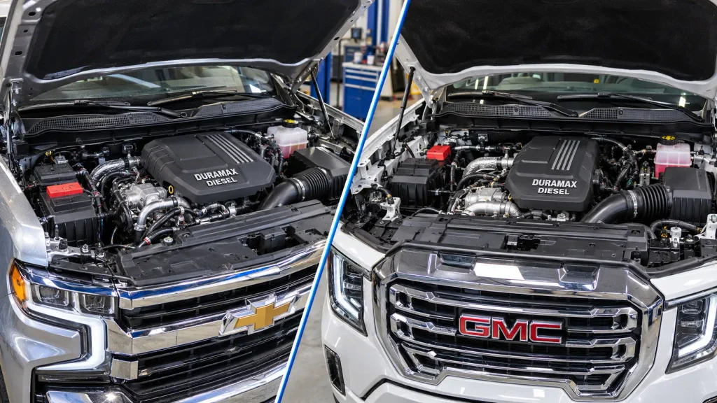
The 2020–2022 LM2 and 2023–2026 LZ0 engines share several sensor locations, but their components and electrical references are not identical.
This guide identifies the major sensors using General Motors component IDs, physical mounting locations, and model-specific service information.
3.0L Duramax Sensor Location Guide


Find the correct sensor zone first, then match the GM component ID. For Silverado 1500 and Sierra 1500 pickups.
3 Sensor Zones to Check


A zone-based locator, not a scaled engine diagram. Driver/passenger directions refer to US-market trucks.
Upper Engine Bay
Rear Engine Area
Exhaust & Underbody


GM IDs identify components, not fault codes. Exact access varies with engine variant and installed equipment.
LM2 vs LZ0: Do Not Mix Up These Sensors
The same sensor function can use a different GM identifier or location.
Multifunction intake air sensor, inside air-cleaner assembly
Right-side engine compartment, on exhaust ahead of turbo vane actuator
Mass airflow sensor mounted to air-cleaner lid
Right underbody, near transmission crossmember and particulate filter
Identify the Correct Sensor in 4 Steps
Use the diagram as an orientation guide, not as a replacement for service diagnostics.
Confirm LM2 or LZ0 and model year.
Use the exact B-series sensor identifier.
Locate intake, rear engine or exhaust area.
Check the OEM locator and diagnose before replacement.
Which 3.0 Duramax Engine Does Your Truck Have



The 3.0L Duramax inline-six turbo-diesel has two main generations in Silverado 1500 and Sierra 1500 pickups. Identifying the engine is the first step toward selecting the correct sensor diagram.
| Engine Code | Pickup Model Years | Vehicles |
|---|---|---|
| LM2 | 2020–2022 | Silverado 1500 and Sierra 1500 |
| LZ0 | 2023–2026 | Silverado 1500 and Sierra 1500 |
Full-size GM SUVs followed a different transition schedule. Some 2023–2024 diesel SUVs still used the LM2 even though the pickups had already switched to the LZ0.


GM’s engine Regular Production Option (RPO) code provides a more reliable identification method than model year alone. Check the vehicle’s equipment information or use the VIN with a GM dealer or compatible parts catalog.
For engine ratings, applications, and other differences, see our 3.0L Duramax LM2 and LZ0 specifications.
3.0 Duramax Sensor Location Diagram Quick Reference



The following tables provide a sensor-location map for the LM2 and LZ0 engines. Locations are described using GM’s component identification system.
Left and right refer to the truck’s sides when seated facing forward. On US-market trucks, left is the driver’s side and right is the passenger’s side.


LM2 Sensor Location Map
| Sensor | GM ID | Location |
|---|---|---|
| MAP and intake temperature | B65 | Left side of intake manifold, near fuel pressure regulator 1 |
| Multifunction intake air sensor | B75C | Left-front engine compartment, inside air-cleaner assembly |
| Fuel rail pressure | B47B | Top of engine, mounted to fuel rail |
| Crankcase pressure | B321 | Right-rear valve cover |
| Camshaft position | B23 | Right-rear engine block, above transmission bellhousing |
| Oil temperature | B36 | Right-rear lower crankcase |
| Oil pressure | B37B | Right-rear lower crankcase, behind B36 |
| DPF differential pressure | B154 | Right-side engine compartment, associated with exhaust assembly |
| NOx sensor 1 | B195A | Exhaust pipe at upper left-rear engine |
| NOx sensors 2 and 3 | B195B/B195C | Exhaust system underneath truck |
These locations follow GM’s 2022 Silverado 1500 LTD Electrical Body Builder Manual.
The LM2 left-rear engine diagram appears on printed page 7-996. The manual also contains engine component locators, a master electrical component list, and individual connector views.
LZ0 Sensor Location Map


| Sensor | GM ID | Location |
|---|---|---|
| MAP and intake temperature | B65 | Left-side intake manifold, near fuel pressure regulator 1 |
| Mass airflow | B75 | Left-front engine compartment, air-cleaner lid |
| Charge-air temperature inlet | B193A | Left side of charge-air cooler |
| Charge-air temperature outlet | B193B | Front of charge-air cooler |
| Fuel rail pressure | B47B | Top of engine, mounted to fuel rail |
| Crankcase pressure | B321 | Right-rear valve cover |
| Camshaft position | B23 | Right-rear engine block, above transmission bellhousing |
| Crankshaft position | B26 | Rear engine area, identified in right-front component locator |
| Oil temperature | B36 | Right-rear lower crankcase |
| Oil pressure | B37B | Right-rear lower crankcase, behind B36 |
| DPF differential pressure | B345P | Right underbody, near transmission crossmember and particulate filter |
| NOx sensor 1 | B195A | Exhaust pipe at upper left-rear engine |
| NOx sensors 2 and 3 | B195B/B195C | Exhaust system underneath truck |
These positions follow GM’s 2026 Silverado 1500 Electrical Body Builder Manual.
For labeled LZ0 illustrations, locate these printed pages:
- Page 8-838: Engine Components Left Rear
- Page 8-840: Engine Components Right Front
- Page 8-841: Engine Components Exhaust Sensors
These diagrams show the actual components with numbered callouts. Use the matching figure and its legend together, because a connector can be hidden behind an intake duct or another engine component.
Where Are LM2 and LZ0 Intake Sensors Located


The main intake sensors measure airflow, manifold pressure, and charge-air temperature. They are not interchangeable, even when their electrical connectors look similar.
MAP and Intake Temperature Sensor
The B65 Manifold Absolute Pressure and Intake Air Temperature sensor is mounted on the left side of the intake manifold, close to fuel pressure regulator 1.



GM identifies this location for both LM2 and LZ0 applications. The sensor combines manifold pressure and intake-air temperature measurement.
To locate it, identify the intake manifold and follow its left side toward the fuel-system components. Look for the small electrical sensor mounted directly to the manifold rather than a sensor installed in the air-filter housing.
The MAP measurement helps the Engine Control Module (ECM) monitor pressure in the intake manifold.
If a MAP-related trouble code appears, inspect the connector, wiring, and sensor passage before assuming the sensor needs replacement.
Our boost pressure sensor location guide explains the differences between intake manifold pressure and other boost-system measurements.
Mass Air Flow Sensor
The Mass Air Flow (MAF) sensor measures the amount of air entering the engine.
On the LM2, GM identifies the B75C Multifunction Intake Air Sensor inside the air-cleaner assembly at the left front of the engine compartment.
On the LZ0, the corresponding GM component is identified as B75 and mounted to the air-cleaner lid.
Start at the airbox rather than searching around the cylinder head. Locate the sensor connector on the air-cleaner assembly and match its component designation to the correct manual.
Charge Air Temperature Sensors
The charge-air cooler has separate temperature measurements for air entering and leaving the cooler.
GM identifies these two positions on the documented LM2 and LZ0 layouts:
- B193A: Charge Air Cooler Air Temperature Sensor Inlet, mounted to the cooler’s left side.
- B193B: Charge Air Cooler Air Temperature Sensor Outlet, mounted to the front of the cooler.
The two sensors monitor different points in the charge-air path. Compare the connector location with the appropriate GM diagram before disconnecting either one.
Where Are 3.0 Duramax Fuel Sensors Located
The fuel system has multiple pressure-monitoring and control components. The fuel rail pressure sensor must not be confused with a low-pressure supply sensor or a fuel pressure regulator.
Fuel Rail Pressure Sensor


The B47B Fuel Rail Pressure Sensor is mounted to the fuel rail at the top of the engine on documented LM2 and LZ0 applications.
It measures pressure in the common-rail system and provides feedback to the ECM.
To identify it, first locate the fuel rail and its electrical connection. Do not identify the sensor solely by a nearby connector or the shape of another fuel-system component.
The LM2 and LZ0 service information also distinguishes B47B from the fuel pressure regulators designated Q18A, Q18B, and Q18C.
Low Pressure Fuel Sensor
The low-pressure fuel sensor uses the GM identifier B47 and is separate from the B47B fuel rail sensor.
On the 2022 Silverado 1500 LTD LM2 reference, GM places B47 on top of the fuel tank, ahead of the rear axle.
The 2026 LZ0 reference places B47 on the right inboard frame rail, behind the fuel filter.
This difference makes the engine generation important when investigating a supply-side fuel pressure issue.
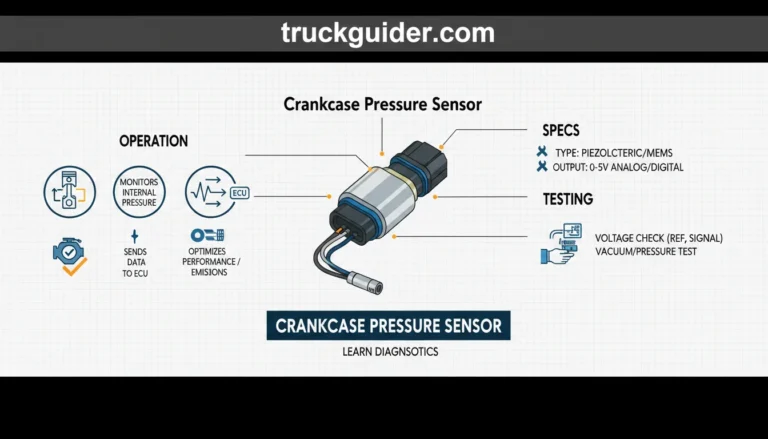
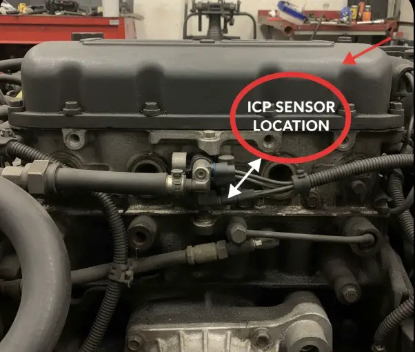
Crankcase Pressure Sensor
The B321 Crankcase Pressure Sensor is installed at the rear of the engine, on the right-rear side of the valve cover.
Both the LM2 and LZ0 component lists identify this rear-engine location.
The sensor monitors crankcase pressure rather than fuel pressure. Access may be obstructed by adjacent intake and charge-air components.
For related symptoms, identification details, and inspection guidance, see our crankcase pressure sensor location guide.
Where Are 3.0 Duramax Crankshaft and Camshaft Sensors Located
The crankshaft and camshaft position sensors supply timing and rotational-position information to the ECM. Both can be harder to access than the intake sensors.
Crankshaft Position Sensor
The Crankshaft Position (CKP) sensor uses component identifier B26.
GM’s 2026 LZ0 right-front engine component locator identifies B26 near the rear-engine component group, alongside the starter and lower engine components.
The correct reference is the rear-engine area, not the front accessory-drive cover used in diagrams for unrelated Duramax generations.
For the LM2, GM’s 2022 electrical manual separately identifies the B26 sensor and its three-terminal connector.
Use the exact engine-specific component locator to determine access. Connector visibility may differ depending on surrounding shields and installed equipment.
Camshaft Position Sensor
The Camshaft Position (CMP) sensor is identified as B23.
GM places it at the rear center of the engine compartment, mounted to the right-rear side of the engine block above the transmission bellhousing.
This location is documented for the LM2 and LZ0 engines.
The bellhousing is the useful landmark because the sensor is farther back than the intake and fuel components.
Inspect the connector and nearby harness routing before considering sensor removal. A crankshaft or camshaft correlation fault can also involve wiring, mechanical timing, or another related condition.
Where Are LZ0 Temperature and Oil Sensors Located
The 3.0L Duramax uses multiple temperature and oil-monitoring sensors. Similar names do not necessarily indicate the same mounting position.
Engine Coolant Temperature Sensors
The LZ0 component list identifies several coolant temperature monitoring points.
B34 Engine Coolant Temperature Sensor is mounted to the left-front side of the engine block, beneath the air-cleaner outlet front duct.
B34B Engine Coolant Temperature Sensor 2 is positioned at the right front of the engine, mounted to the water-pump inlet pipe.
On the LM2, coolant sensors include different numbered references such as B34A, B34B, and B34E. Confirm the appropriate diagram before using an LZ0 sensor label on an LM2.
Engine Oil Temperature Sensor
The B36 Engine Oil Temperature Sensor is installed at the right-rear side of the lower crankcase.
GM locates it forward of the B37B oil pressure sensor on the documented LM2 and LZ0 layouts.
This distinction matters because the two sensors monitor different properties and occupy nearby positions.
Engine Oil Pressure Sensor
The B37B Engine Oil Pressure Sensor is located at the right-rear lower crankcase, behind B36.
The correct identification is based on its mounting location and electrical connector, not on an assumption that every oil-related sensor is next to the oil filter.
If the truck reports an oil-pressure warning, follow the correct diagnostic procedure. Do not operate an engine with suspected inadequate lubrication simply to test a sensor.
Where Are LM2 and LZ0 Exhaust Sensors Located
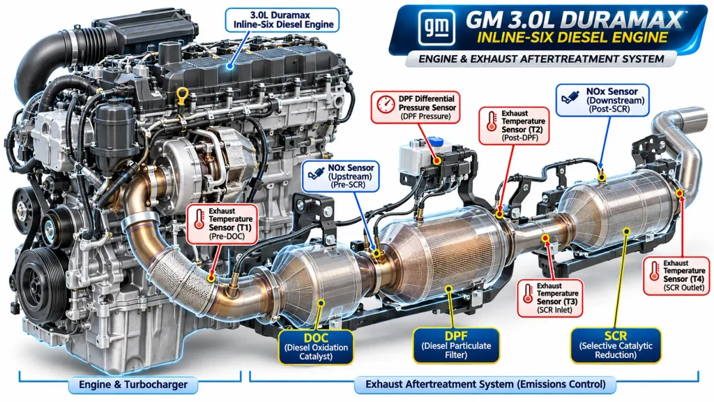
The exhaust aftertreatment system contains sensors that monitor nitrogen oxides, exhaust temperature, and particulate filter operation.
A complete 3.0 Duramax sensor location diagram must therefore include the exhaust system, not just the engine bay.
NOx Sensor Locations
Nitrogen Oxides (NOx) sensors monitor emissions-related conditions at different exhaust-system positions.
GM identifies three NOx sensor designations in the documented LM2 and LZ0 component references.
| Sensor | GM ID | Location |
|---|---|---|
| NOx sensor 1 | B195A | Upper left-rear engine, attached to exhaust pipe |
| NOx sensor 2 | B195B | Under truck, at the particulate-filter section |
| NOx sensor 3 | B195C | Under truck, attached farther along exhaust piping |
The LZ0 master component list locates B195B at the middle of the diesel particulate filter.
Sensor numbering matters. Do not replace NOx sensor 2 when the diagnostic system identifies NOx sensor 1 or 3.
Follow the exhaust routing and confirm the sensor identification using the correct service diagram.
DPF Differential Pressure Sensor
The Diesel Particulate Filter (DPF) differential pressure sensor monitors the pressure relationship across the particulate-filter system.
One of the important LM2-to-LZ0 differences is the component designation and documented position.
LM2 B154: GM’s 2022 reference places the DPF exhaust differential pressure sensor in the right-side engine compartment, associated with the exhaust assembly near the turbocharger vane-position actuator.
LZ0 B345P: GM’s 2026 reference places the particulate-filter exhaust differential pressure sensor underneath the truck, on the right side near the transmission crossmember.
The LZ0 sensor is mounted in the particulate-filter area.
This difference is why a generic Duramax DPF sensor diagram may not match either 3.0L generation.
Inspect associated pressure lines and electrical connections according to the correct service procedure. A pressure-related diagnostic code does not prove the sensor itself has failed.
Exhaust Temperature and Particulate Matter Sensors
The LM2 service information identifies exhaust temperature sensor positions including B131A, B131B, and B131C.
The LZ0 uses exhaust temperature sensing modules identified in GM documentation as B359 and B359B.
The LZ0 exhaust component locator also identifies the B136 Exhaust Particulate Matter Sensor.
These components occupy different areas of the aftertreatment system. Identify them by function, GM component number, and physical exhaust position before ordering parts.
Do not begin exhaust-sensor work until the exhaust system has cooled completely.
How to Match LZ0 Sensor Trouble Codes to Locations
A Diagnostic Trouble Code (DTC) indicates a circuit, performance issue, or operating condition. It is not automatic confirmation of a failed sensor.
GM’s May 2026 bulletin PIP6119 addresses a particular issue affecting 2024–2026 Silverado 1500 and Sierra 1500 trucks equipped with the 3.0L LZ0.
The bulletin identifies the following codes appearing during diagnosis:
| DTC | Diagnostic Context |
|---|---|
| P00DF | Included in the GM bulletin’s affected code group |
| P0101 | Included in the affected code group |
| P00E9 | Included in the affected code group |
| P0186 | Included in the affected code group |
| P1428 | Included in the affected code group |
GM reports that affected trucks may display an erroneous 419°F fuel-temperature reading.
The bulletin identifies the B65 MAP/IAT sensor as a possible cause when these conditions occur. That does not mean every truck storing one of these codes has a defective MAP sensor.
GM directs technicians to follow service diagnostics and, when appropriate, compare B65 resistance readings against the published temperature-resistance specifications.
The details are documented in GM Service Bulletin PIP6119.
For other trouble codes, use the specific GM diagnostic chart to distinguish sensor faults from wiring, fuel-system, boost, or exhaust problems.
How to Find 3.0 Duramax Sensors Safely
Use a consistent identification process before disconnecting any sensor.
- Confirm the engine code. Identify whether the truck has an LM2 or LZ0 and note its model year.
- Record the diagnostic information. Save stored trouble codes and relevant scan-tool readings before clearing them.
- Match the GM component ID. Find the sensor in the appropriate engine or exhaust locator diagram, then identify its physical mounting landmark.
- Inspect before replacing. With the system made safe according to service instructions, check the connector, wiring, visible damage, and related components before determining whether replacement is necessary.
Avoid working around a running engine’s belts and fans. Exhaust and turbocharger components can remain dangerously hot after shutdown.
Never loosen high-pressure fuel rail connections without following the manufacturer-approved depressurization procedure. A common-rail diesel fuel system can retain hazardous pressure.
Use proper lifting and support equipment for under-truck inspection. A floor jack alone is not sufficient support.
If a sensor is difficult to reach or requires fuel-system disassembly, use a qualified diesel technician.
Which 3.0 Duramax Sensor Diagram Should You Use
The correct 3.0 duramax sensor location diagram depends on the engine generation and the specific sensor being inspected.
For a 2020–2022 Silverado or Sierra 1500 with the LM2, use the LM2 component locators. These identify the intake manifold sensor, rear-engine monitoring components, fuel sensors, and the earlier DPF pressure-sensor arrangement.
For a 2023–2026 pickup with the LZ0, use the corresponding LZ0 diagrams. The 2026 GM manual is particularly useful because it separates left-rear engine, right-front engine, and exhaust sensor locations.
Do not assume that a sensor on a 6.6L Duramax V8 occupies the same position on the 3.0L inline-six.
Start with the engine code, find the GM sensor identifier, and match the physical connector against the appropriate service reference. Diagnose the circuit before replacing the component.
5 Common Questions About 3.0 Duramax Sensors
Where Is the MAP Sensor on a 3.0 Duramax?
The MAP sensor is mounted on the left side of the intake manifold near fuel pressure regulator 1. GM identifies this combined manifold pressure and intake-air temperature sensor as B65 on LM2 and LZ0 applications. Verify the engine version before removing surrounding components.
Where Is the Crankshaft Position Sensor on a 3.0 Duramax?
The crankshaft position sensor is identified as B26. The LZ0 component locator places it in the rear-engine component group, while LM2 service information provides its separate connector reference. Consult the engine-specific locator and access procedure rather than an older 6.6L Duramax diagram.
Are LM2 and LZ0 Sensor Locations the Same?
No, not every sensor has the same designation or location. Both engines have a B65 MAP/IAT sensor on the intake manifold, but their MAF designations and DPF differential pressure sensor locations differ. Always use the correct model-year reference.
Where Are the NOx Sensors on a 3.0 Duramax?
NOx sensor 1 is located on the exhaust pipe near the upper left-rear engine area. NOx sensors 2 and 3 are mounted farther along the exhaust system underneath the truck. Confirm the sensor number through the applicable GM exhaust diagram before attempting replacement.
Where Is the Fuel Rail Pressure Sensor on a 3.0 Duramax?
The B47B fuel rail pressure sensor is mounted on the fuel rail at the top of the engine. This location is documented on LM2 and LZ0 applications. It should not be confused with the separate low-pressure fuel sensor or the fuel pressure regulators.