3.0 Power Stroke Sensor Location Diagram: Full Guide 2026

The 3.0 Power Stroke sensor location diagram for the 2018–2021 Ford F-150 separates the engine’s sensors into four areas: the upper engine, right-hand fuel rail, left side of the engine, and exhaust aftertreatment assembly.
The MAF, MAP, and charge-air cooler temperature sensors are associated with airflow; the FRP sensor monitors the high-pressure fuel rail; and the CKP sensor requires access from the left-hand engine area.


This guide uses Ford’s 2018 3.0L Power Stroke V6 electronic-engine-controls component list as its primary locator reference. The truck’s VIN and corresponding model-year service information remain essential when identifying connectors or ordering replacement parts.
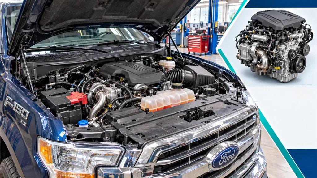
3.0L Power Stroke Sensor Locator


Ford F-150 diesel, 2018-2021 coverage. Start with the correct service view, then confirm the exact component using your VIN-specific manual.
Upper Engine View
Under-hood control sensors identified in the 2018 reference
MAF
MAP
CAC temperature
EOP
ECT
CHT
CMP
Fuel pressure + temperature
Exhaust pressure
Also shown: fuel pressure control valve (an actuator, not a sensor).
Fuel Rail, RH View
Right-hand side in the 2018 component map
Year-specific reference. Confirm the location before ordering or removing a part.
Engine Side, LH View
Left-hand side, driver’s side on US F-150
The 2020 service procedure begins with the LH fender splash shield.
Exhaust Aftertreatment View
Underbody component groups, not a to-scale exhaust sequence
The listed exhaust components follow the 2018 reference; later-year sensor counts and routing require a VIN check.
Verify the Correct Sensor in 4 Steps
Where Are the Main 3.0L Engine Sensors Located


Ford offered the 3.0L Power Stroke V6 Turbo Diesel in the F-150 from 2018 through 2021. Its common-rail fuel injection and exhaust aftertreatment systems differ from those on the older 7.3L and 6.0L Power Stroke engines. Ford’s 2021 F-150 technical specifications identify the 3.0L as a turbocharged, intercooled V6 using common-rail injection.
The following locations are component groups, not approximate coordinates on a generic V6 picture:
| Service Diagram View | Sensors or Components to Identify |
|---|---|
| Upper engine | MAF, charge-air cooler temperature, EOP, ECT, MAP, CHT, fuel pressure/temperature, exhaust pressure, CMP |
| Right-hand fuel rail | FRP sensor in the 2018 service illustration |
| Left-hand engine side | CKP sensor |
| Exhaust system | EGT11–EGT14, NOx sensors, particulate matter sensor and module, DPF differential-pressure sensor |
In Ford terminology, LH and RH refer to the sides of the truck when facing forward from the driver’s seat. In a US-market F-150, LH is the driver’s side and RH is the passenger’s side. A photograph taken from in front of the grille reverses their appearance.


How to Read the 3.0 Power Stroke Sensor Location Diagram


The following Markdown locator organizes components by Ford service-manual viewing area. It is a reference map, not a scale drawing or a substitute for the VIN-specific illustrations. The exact position of each plug or bracket should be confirmed before removing anything.
The 2018 3.0L electronic-engine-controls component-location reference lists these groups in separate views. Use it to match the component labels, rather than borrowing an illustration from a 6.7L or 7.3L engine.
Important: The exhaust view identifies monitored components but does not establish their physical sequence in the text map. Trace the exhaust assembly using the correct model-year drawing.


Where Are the MAF MAP and CAC Sensors


These three sensors monitor different parts of the intake-air system. Follow the air intake and charge-air plumbing as landmarks rather than identifying a sensor by its connector shape alone.
Mass Air Flow Sensor Location
The mass air flow (MAF) sensor is in the fresh-air intake path associated with the air-cleaner assembly. It measures the air entering the engine before that air is compressed by the turbocharger. Start at the air-filter housing and follow the intake duct toward the turbocharger to identify the sensor’s installed position.
A contaminated sensing element, disconnected plug, intake restriction or air leak may cause an airflow-related fault. Inspect the housing and connector before assuming the MAF sensor has failed.
Manifold Absolute Pressure Sensor Location
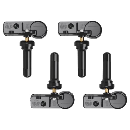
The manifold absolute pressure (MAP) sensor is on the intake manifold at the upper engine. Ford’s 2018 replacement procedure begins by removing the engine appearance cover, then disconnecting the sensor’s connector and harness retainer.



The MAP signal helps the powertrain control module (PCM) evaluate intake pressure. If you’re investigating low boost, compare the MAP reading with the truck’s other pressure data. Our boost pressure sensor location guide explains the general difference between boost measurements and manifold absolute pressure; use the 3.0L-specific reference for the actual mounting position.
Charge Air Cooler Temperature Sensor Location


The charge-air cooler (CAC) temperature sensor monitors the temperature of compressed intake air after cooling. Look along the charge-air plumbing between the intercooler system and the engine intake, then confirm the precise point with the service illustration.
Do not confuse the CAC temperature sensor with the MAF sensor in the air-cleaner tract. They monitor air at different points and are not interchangeable.
Where Is the 3.0L Fuel Rail Pressure Sensor


The fuel rail pressure (FRP) sensor measures pressure in the high-pressure common-rail system. In the 2018 Ford electronic-controls illustration, it is identified in the right-hand fuel-rail view. The service procedure for that year refers to the FRP sensor as serviced with the RH fuel-rail assembly.
Some later general Ford diesel descriptions use a different rail-side reference. Treat the 2018 RH designation as year-specific, and verify the 2019–2021 layout against the vehicle VIN rather than assuming every model year matches the earlier drawing.
Fuel Pressure and Temperature Sensor
The separate fuel pressure and temperature sensor appears in Ford’s upper-engine view. It monitors the fuel-supply side of the system and must not be mistaken for the FRP sensor on the high-pressure rail. A pressure control valve is also marked nearby in the component list, but that valve controls fuel flow or pressure rather than measuring it.
Do not loosen the FRP sensor, fuel rail, or any high-pressure fuel fitting to identify a part. Diesel fuel under pressure can penetrate skin and cause severe injury. Diagnose the circuit with the correct scan data and repair procedure before any disassembly.
This engine also differs from the older 7.3L Power Stroke ICP sensor system, which measures high-pressure oil for hydraulic injector actuation. The 3.0L uses common-rail fuel pressure monitoring, not a 7.3L-style ICP/IPR arrangement.
Where Are the CKP CMP and Temperature Sensors
The crankshaft position (CKP) and camshaft position (CMP) sensors provide engine-position information. Ford identifies the CMP in the upper-engine view and the CKP in the left-hand engine-side view on the 2018 3.0L Power Stroke.
Crankshaft Position Sensor Location
The CKP sensor is on the left-hand side of the engine, not on the upper intake plumbing. Ford’s 2020 F-150 3.0L CKP removal procedure specifies removing the LH fender splash shield and CKP cover, with additional access involving the oil-level indicator tube.
That is useful for locating the component, but it is not permission to remove covers while the truck is unsupported. Secure the vehicle and use the full procedure if replacement becomes necessary.
Camshaft Position Sensor Location
The CMP sensor is identified from the upper-engine view. The 2018 service procedure calls for removing the appearance cover and air cleaner for access. This distinguishes it from the CKP, whose service access is through the LH wheel-well area.
If the engine cranks without starting, inspect both engine-position data and the relevant wiring before buying either sensor. A missing signal can have several electrical or mechanical causes.
Engine Temperature and Oil Sensors


Ford also identifies three separate engine-condition sensors in the top-view component list:
- ECT: Engine coolant temperature sensor, associated with the engine’s coolant passages.
- CHT: Cylinder head temperature sensor, installed in the cylinder-head area.
- EOP: Engine oil pressure sensor, associated with the engine’s lubrication system.
Their similar electrical connectors do not indicate interchangeable functions. Use the Ford identification view before disturbing the cooling or lubrication system.
Where Are the EGT NOx and DPF Sensors
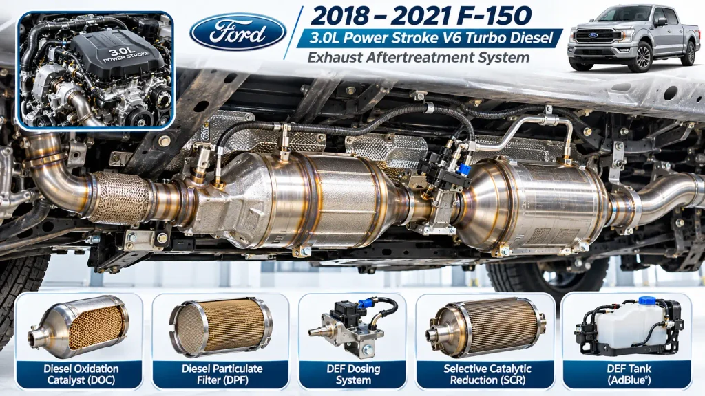
The exhaust sensors are distributed along the 3.0L Power Stroke’s aftertreatment assembly under the truck, rather than grouped on the cylinder heads. The diesel oxidation catalyst, diesel particulate filter (DPF), diesel exhaust fluid (DEF) dosing system and selective catalytic reduction (SCR) catalyst are the main landmarks.
Exhaust Gas Temperature Sensor Locations
The 2018 service illustration identifies four exhaust gas temperature sensors, EGT11 through EGT14. Each uses a probe fitted to a particular exhaust sampling point. Their signals help the PCM monitor aftertreatment temperatures, including conditions relevant to DPF regeneration.
The number is part of the diagnostic identifier. Do not select a replacement EGT sensor by proximity alone; match its service designation and connector routing.
Nitrogen Oxides Sensor Locations
The 2018 diagram labels NOx11 and NOx12 and their associated control modules. The sensor probe is installed in the exhaust stream, while its electronics module is mounted separately. Those parts must be identified as a matched assembly where the Ford procedure requires it.
The available 2021 service index also lists a NOx13 service procedure. For that reason, do not assume that a two-sensor 2018 diagram establishes the NOx sensor count for every 2021 configuration. Confirm your VIN and the relevant exhaust layout.
Diesel Particulate Filter Pressure Sensor
The DPF differential-pressure sensor is associated with the filter and its pressure connections. Ford’s 2018 removal procedure includes access beneath the truck and work around the transmission housing cover and sensor bracket. It is not the same component as the upper-engine exhaust pressure sensor.
Our DPF pressure sensor location guide explains how differential pressure is used to evaluate filter restriction. For the 3.0L Power Stroke, identify the actual sensor and pressure fittings using the Ford-specific service view before disconnecting anything.
How to Verify a Sensor in Four Steps
Identifying the right sensor is a four-step process. Follow the steps in order before deciding that a replacement part is required.
- Confirm the truck and engine. Check the model year, VIN and the 3.0L Power Stroke V6 designation. Do not rely on a 6.7L Super Duty diagram.
- Choose the correct view. Use the upper-engine illustration for MAF, MAP, CMP and temperature-related components. Use the RH fuel-rail or LH engine-side view for FRP and CKP where that designation matches your model year.
- Identify the component without disassembly. With the engine off and cool, match the sensor body, connector, retaining hardware and surrounding components. A label or part marking is more reliable than connector color alone.
- Verify the fault with scan data. Record the diagnostic trouble code, freeze-frame data and related sensor readings. Compare those readings with the matching Ford diagnostic procedure before ordering parts.
A correct visual match tells you which sensor you found. It does not establish whether the sensor itself is faulty.
Which Sensor Codes Identify the 3.0L System
Diagnostic trouble codes (DTCs) direct testing toward a circuit or system. They do not automatically mean a sensor needs replacing. The following are examples of sensor-related codes used in Ford diesel diagnostic procedures:
| DTC | Diagnostic Area | First Check |
|---|---|---|
| P0101 | MAF circuit range or performance | Intake leaks, restrictions, MAF signal |
| P0102 | MAF circuit low input | Connector, wiring, signal |
| P0191 | Fuel rail pressure range or performance | Actual versus commanded pressure, fuel supply |
| P2452 | DPF pressure sensor circuit | Pressure sensor circuit and related connections |
| P2453 | DPF pressure sensor range or performance | Pressure response, restrictions, leaks |
Ford’s 2020 3.0L F-150 DPF diagnostic procedure specifically directs P2452 and P2453 into a diagnostic test sequence rather than immediately replacing the sensor. That distinction matters when a blocked pressure passage, damaged circuit or filter issue produces a similar warning.
The precise applicability of a code, its subcode and the required test depend on the model year and PCM calibration. A Ford-capable scan tool is preferable to guessing from a generic code description.
What to Check Before Replacing Any Sensor
Before replacing a suspected sensor, inspect the connector seal, wiring harness and nearby plumbing. Look for damaged clips, corrosion, rubbed wiring, disconnected hoses and evidence of leakage. An intake leak can change MAF or MAP readings without either sensor being defective.
For exhaust sensors, work only after the exhaust has cooled completely. DPF regeneration can make the aftertreatment assembly extremely hot. Do not disconnect exhaust fittings on a hot system or crawl beneath a truck supported only by a jack.
For fuel-system faults, never crack open high-pressure common-rail fittings to check pressure. Use approved scan-tool testing and Ford’s depressurization and service procedures. If specialized access or diagnosis is necessary, use a qualified diesel repair shop.
What the 3.0L Sensor Diagram Helps Confirm
A useful 3.0 Power Stroke sensor location diagram separates upper-engine sensors from the fuel-rail, CKP and exhaust-system components. On the 2018 Ford reference, the FRP sensor is in the RH fuel-rail view and the CKP is in the LH engine-side view. MAF, MAP, CMP and engine-condition sensors appear in the upper-engine reference, while EGT, NOx, PM and DPF sensors belong to the exhaust system.
Use those groupings to find the correct area, then confirm the sensor’s actual identity against the service information for your truck’s VIN. Once the component is identified, use fault codes and live sensor data to decide what needs testing. That prevents an incorrect sensor replacement based on a generic diagram.
Frequently Asked Questions About 3.0L Power Stroke Sensors
Where Is the MAP Sensor on a 3.0 Power Stroke


The MAP sensor is on the intake manifold in the upper-engine area. Ford’s 2018 service procedure includes removing the engine appearance cover to reach the sensor. Confirm the installed connector and retaining hardware using your model-year diagram.
Where Is the Fuel Rail Pressure Sensor Located
The 2018 3.0L Power Stroke component map identifies the FRP sensor in the right-hand fuel-rail view. Use the VIN-specific illustration for later model years because generic Ford diesel descriptions may identify different rail locations. Never loosen a high-pressure connection merely to identify it.
Where Is the Crankshaft Position Sensor Located
The CKP sensor is on the left-hand side of the engine. The 2020 Ford removal procedure accesses it by removing the left-hand fender splash shield and its sensor cover, with additional clearance steps. Follow the complete service procedure if the sensor must be replaced.
How Many EGT Sensors Are on the 3.0 Power Stroke
The 2018 3.0L Power Stroke exhaust component view lists four EGT sensors: EGT11, EGT12, EGT13 and EGT14. These are installed at different exhaust monitoring points, not together in one housing. Identify the required sensor by its Ford designation and model-year exhaust drawing.
Does the 3.0 Power Stroke Have a 7.3L Style ICP Sensor
No. The 3.0L Power Stroke uses common-rail diesel injection, with fuel-pressure sensing that differs from the older 7.3L’s hydraulic electronic unit injection system. A 7.3L ICP or IPR location diagram should not be used to identify parts on the 3.0L V6.