46RE Transmission Wiring Diagram: Easy Setup Guide
The 46re transmission wiring diagram centers on an 8-pin connector that controls the governor pressure solenoid, transducer, and overdrive/lockup solenoids. By identifying the hot wire for 12V power and the common terminal for sensor signals, you can troubleshoot limp mode, erratic shifting, or failure to engage fourth gear.
📌 Key Takeaways
- Maps the 8-pin interface between the PCM and internal solenoids
- Critical for diagnosing governor pressure and overdrive malfunctions
- Ensures correct voltage delivery to the transmission control system
- Helps distinguish between electronic sensor failure and mechanical wear
- Essential reference for replacing the internal wiring harness or sensors
When dealing with the complexities of the Chrysler A518 family, specifically the 46RE, having a precise 46re transmission wiring diagram is the difference between a successful repair and a permanent limp-mode nightmare. For DIY enthusiasts and professional mechanics alike, the electronic governor pressure control system in these transmissions represents a significant shift from the purely hydraulic units of the past. This article provides a deep dive into the wiring schematics, pin identification, and color-coding necessary to diagnose shifting issues, solenoid failures, and sensor malfunctions. By the end of this guide, you will understand how the Powertrain Control Module (PCM) communicates with your transmission to manage shift points, torque converter lockup, and overdrive engagement.
Comprehensive Breakdown of the 46RE Transmission Wiring Diagram
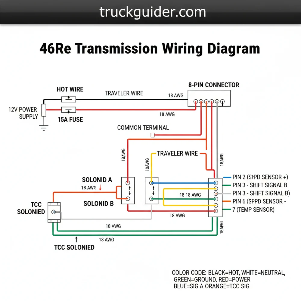
The 46RE transmission utilizes an electronic control system that primarily interfaces through an 8-pin connector located on the driver’s side of the transmission case, just above the pan rail. Understanding the 46re transmission wiring diagram requires a breakdown of this specific connector, as it manages the most critical electronic functions: the governor pressure solenoid, the governor pressure transducer, and the two shift/lockup solenoids.
The diagram identifies the internal harness as a bridge between the external vehicle wiring and the sensitive electronic components submerged in transmission fluid. The main 8-pin connector is keyed to prevent incorrect orientation, and each pin corresponds to a specific circuit. Typically, Pin 1 and Pin 8 are the power and ground supply for the governor pressure solenoid. The transducer, which acts as a feedback loop for the PCM, uses a 5-volt reference signal, a signal return (ground), and a pressure signal wire.
In the 46RE system, the PCM does not directly “shift” the gears like a modern 6-speed. Instead, it varies the voltage to the governor pressure solenoid to simulate a mechanical governor. If your wiring diagram shows a loss of the 5-volt reference, the transmission will default to third gear (Limp Mode).
Beyond the 8-pin connector, the 46re transmission wiring diagram must also account for the Neutral Safety Switch (NSS), also known as the Park/Neutral Position Switch. This is a 3-pin connector located further back on the case. It handles the ground path for the starter relay and provides the signal for the reverse lights. Furthermore, the Output Speed Sensor (OSS) sits at the rear of the extension housing, providing a frequency signal to the PCM that translates to vehicle speed, which is crucial for determining shift timing.
Color coding varies slightly between vehicle models (such as the Ram 1500 versus the Jeep Grand Cherokee), but the pin positions remain constant. For instance, a common configuration sees a Violet/White wire providing the 5-volt reference, while an Orange/Black wire serves as the governor pressure signal. Always verify the gauge of the wire before performing a bypass or repair, as signal wires are typically a thinner 18 or 20 gauge, while power wires may be 16 gauge to handle higher current loads.
[DIAGRAM_PLACEHOLDER – 8-Pin Transmission Connector Map: Pin 1: 12V Supply, Pin 2: TCC Solenoid Control, Pin 3: Overdrive Solenoid Control, Pin 4: Governor Pressure Solenoid Control, Pin 5: 5V Transducer Reference, Pin 6: Sensor Ground, Pin 7: Transducer Signal, Pin 8: Thermistor/Temp Signal]
Step-by-Step Guide to Reading and Implementing the Wiring Diagram

Interpreting a 46re transmission wiring diagram can be intimidating if you treat it as a single web of lines. Instead, you should approach it as a series of individual loops. Follow these steps to diagnose or wire your transmission correctly.
- ✓ Identify the Power Source: Locate the “Hot Wire” in your diagram. In the 46RE system, the transmission relay in the Power Distribution Center (PDC) provides a 12V “hot” signal to the solenoids. Use a multimeter to verify 12V at the harness connector when the key is in the ‘On’ position.
- ✓ Check the Common Terminal: In electrical terms, a common terminal often refers to a shared ground or power point. For the 46RE, many solenoids share the same 12V power feed, and the PCM provides the ground to trigger them. This is known as “ground-side switching.”
- ✓ Verify the 5V Reference: The governor pressure transducer requires a clean 5V signal. This is not battery voltage. If you see 12V on this wire, the PCM internal regulator has likely failed, or there is a short to a hot wire elsewhere in the loom.
- ✓ Map the Ground Wire: Ensure the transmission case is properly grounded to the engine block and battery. A poor ground wire connection can cause “ghost” codes, where the transducer reports erratic pressure readings due to electrical noise.
- ✓ Trace the Signal Path: Use the diagram to identify which pin at the transmission connector maps to which pin at the PCM. This is vital for “pinning out” the harness to check for continuity or breaks.
- ✓ Test Solenoid Resistance: Using the diagram to identify the correct pins, measure resistance. A healthy governor solenoid usually shows 3-5 ohms, while the TCC and Overdrive solenoids should be around 30 ohms.
When working with auxiliary wiring or retrofitting these transmissions into older vehicles using standalone controllers, you may encounter terms like “traveler wire” or “brass screw” terminals. While these are more common in household electrical switches, the logic remains the same: the traveler wire represents a signal that moves between two states (like an overdrive on/off toggle), and the connection points must be secure. Ensure all connections use the correct wire gauge—typically 16-18 AWG for automotive transmission circuits—to prevent voltage drops that could lead to erratic shifting.
Never apply 12V directly to the sensor signal wires (Pins 5, 6, or 7). These are low-voltage circuits designed for 5V logic. Applying battery voltage can instantly fry the transducer or the PCM’s input processing circuit.
To begin your installation or repair, you will need a digital multimeter, a set of back-probe pins, and a high-quality wiring diagram specific to your vehicle’s year. Start by disconnecting the battery before unplugging the 8-pin connector to prevent accidental shorts. Inspect the “neutral wire” (logic ground) and ensure no pins are backed out of the plastic housing.
Common Issues & Troubleshooting with the 46RE Wiring

The most frequent issue solved by a 46re transmission wiring diagram is the dreaded “Limp Mode,” where the transmission stays in third gear and will not shift automatically. This is often caused by a break in the governor pressure solenoid circuit. If the PCM detects an open circuit or a short to ground on Pin 4, it cuts power to the transmission relay for safety.
Another common problem is “shuttle shifting,” where the transmission hunts rapidly between gears. This is frequently a result of electrical interference on the transducer signal wire. The 46re transmission wiring diagram helps you identify the sensor ground (Pin 6). If this ground is shared with a high-draw component or has high resistance, the pressure signal will fluctuate, confusing the PCM.
If you are experiencing erratic shifting, check the wiring harness where it passes over the rear of the engine block. Heat cycles often cause the insulation to become brittle, leading to intermittent shorts that won’t always blow a fuse but will disrupt the voltage signals.
If your reverse lights are failing or the truck won’t crank, the 46re transmission wiring diagram points you toward the 3-pin Neutral Safety Switch. The center pin is the ground path for the starter relay. By jumping this center pin to a chassis ground, you can determine if the switch is faulty or if the problem lies deeper in the vehicle’s ignition wiring.
Tips & Best Practices for Transmission Wiring Maintenance
When performing repairs based on a 46re transmission wiring diagram, quality of execution is paramount. The environment under a vehicle is harsh, involving heat, moisture, and vibration. Always use automotive-grade TXL or GXL wire, which features cross-linked insulation that resists melting and chemical degradation.
Regarding connectivity, avoid “vampire” or “T-tap” connectors. These cut into the wire strands and create a point of failure and corrosion. Instead, use heat-shrink butt connectors or, ideally, solder your connections and seal them with adhesive-lined heat shrink tubing. This ensures that the voltage remains stable and the signal wires are protected from the elements.
When routing your harness, follow the factory path. The factory used specific clips to keep the wires away from the exhaust manifold and the moving parts of the shift linkage. If you are replacing the internal harness (the one inside the pan), ensure the wires are tucked neatly into the plastic guides so they aren’t pinched when you bolt the valve body back into place.
Maintenance of the connectors is equally important. Every time you have the 8-pin connector unplugged, inspect it for transmission fluid “wicking.” Occasionally, the internal seal of the solenoid connector fails, allowing pressurized fluid to travel up inside the wires, eventually reaching the PCM. If you see fluid inside the electrical connector, the internal harness must be replaced immediately. Using a small amount of dielectric grease on the outer weather seal of the connector can help prevent moisture intrusion, but avoid globbing it onto the pins themselves, as this can occasionally increase resistance on low-voltage signal circuits.
Understanding the Role of Voltage and Gauge in 46RE Logic
The 46RE is highly sensitive to voltage drops. Because the governor pressure is controlled via Pulse Width Modulation (PWM), the PCM rapidly turns the ground on and off to achieve the desired pressure. If the wire gauge is too thin or the “hot wire” has high resistance due to a corroded terminal, the solenoid will not react quickly enough, leading to soft shifts or burnt clutches.
Always verify the battery and alternator health before blaming the transmission wiring. A failing alternator can introduce “AC ripple” into the DC system. This electrical noise can mimic a faulty speed sensor or transducer signal on your 46re transmission wiring diagram, leading you to replace parts that are perfectly functional. A clean, steady 12.6V static and 14.2V charging voltage are the foundation upon which the transmission’s electronic logic depends.
In summary, the 46re transmission wiring diagram is your roadmap to a healthy drivetrain. By understanding the distinction between the 12V power circuits and the 5V logic circuits, identifying the specific roles of all 8 pins in the main connector, and maintaining the integrity of the ground and signal wires, you can ensure your transmission shifts smoothly for years to come. Whether you are troubleshooting a fault code or performing a complete harness restoration, accuracy and attention to detail in your wiring will always pay off in performance.
Frequently Asked Questions
Where is the 46re connector located?
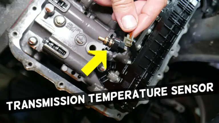
The main 8-pin electrical connector is located on the driver’s side of the transmission case, just above the pan rail. It is oriented vertically, pointing upwards toward the floorboard. Accessing it may require removing the front driveshaft on 4WD models or using a long extension for better clearance.
What does 46re transmission wiring diagram show?
The 46re transmission wiring diagram details the circuitry for the governor pressure solenoid, pressure transducer, and the overdrive/lock-up solenoids. It illustrates how the PCM controls shifts through specific pins, showing the flow from the common terminal to ground wire points to ensure proper gear engagement and fluid regulation.
How many wires does the 46re connector have?
The 46re uses an 8-pin connector for its internal electronics. These pins include power delivery for the solenoids, signal wires for the transducer, and ground wire paths. Understanding the traveler wire concept in these circuits helps in identifying signal movement between the sensor and the vehicle’s computer system.
What are the symptoms of a bad 46re wire harness?
Symptoms include limp mode, where the transmission stays in third gear, or erratic shifting between gears. You might also experience a failure to engage overdrive or the torque converter lock-up. Electrical issues often trigger check engine lights with specific codes like P0753, P1762, or P1763.
Can I repair 46re wiring myself?
Yes, you can replace the internal harness or repair external connector pigtails yourself. By following the 46re transmission wiring diagram, you can use a multimeter to check for 12V at the hot wire and verify ground signals. Basic soldering and heat-shrink skills are required for long-lasting electrical repairs.
What tools do I need for 46re wiring repair?
You will need a digital multimeter for continuity and voltage testing, a set of socket wrenches to remove the transmission pan if replacing internal components, and wire strippers. A high-quality scan tool is also helpful for reading live governor pressure data to confirm the wiring is functioning correctly.