5.9 Cummins Fan Clutch Wiring Diagram: Easy Setup Guide
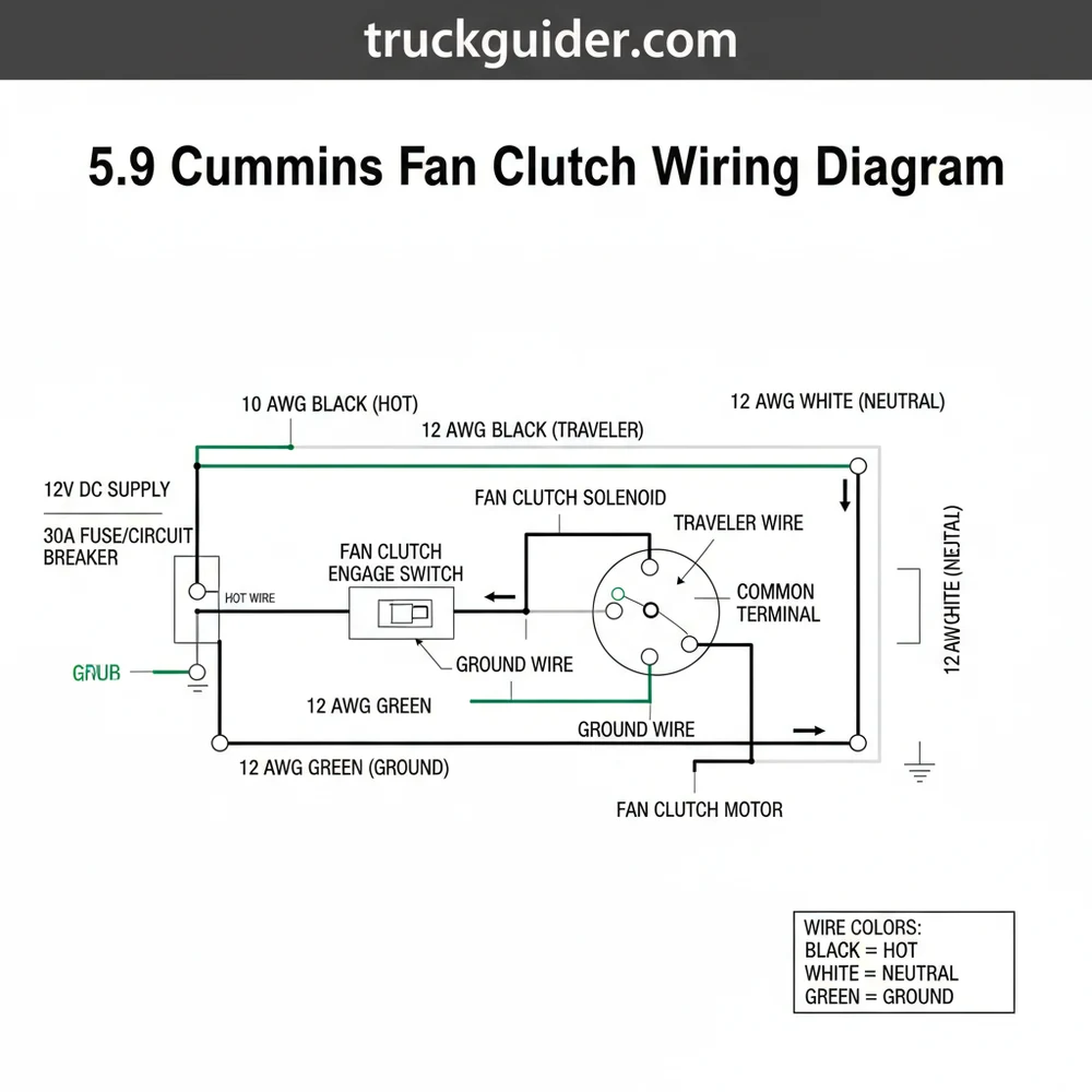
The 5.9 Cummins fan clutch wiring diagram illustrates the six-pin connector layout. It uses a hot wire for power and a ground wire for the circuit. The ECM regulates fan speed by pulse width modulation through a traveler wire to the common terminal, ensuring the viscous clutch engages precisely based on temperature.
📌 Key Takeaways
- Provides a visual map for troubleshooting fan speed sensors and solenoid circuits.
- Identify the 6-pin connector pins to prevent shorting the ECM during testing.
- Always disconnect the battery before testing the fan clutch harness pins.
- Use a multimeter to check for 12V supply at the hot wire location.
- Use this diagram when diagnosing overheating or excessive fan roar issues.
If you are experiencing cooling issues or unusual fan noise in your diesel truck, understanding the 5.9 cummins fan clutch wiring diagram is the first step toward a successful repair. The transition from purely mechanical fan clutches to electronically controlled viscous clutches in the 5.9L Cummins engine allowed for much better fuel efficiency and noise control, but it also introduced a layer of electrical complexity. When the engine control module (ECM) cannot communicate effectively with the fan clutch, the system may default to a “fail-safe” mode where the fan runs at full speed, or worse, it may not engage at all, leading to dangerous overheating. This guide provides a comprehensive breakdown of the wiring architecture, helping you identify every connection point to restore proper cooling performance.
Detailed Description of the 5.9 Cummins Fan Clutch Wiring Diagram
The fan clutch on the 5.9L Cummins typically utilizes a six-pin connector, though in many applications, only five of these pins are actively used. The wiring harness connects the fan clutch assembly directly to the vehicle’s ECM, which sends a pulse-width modulated (PWM) signal to regulate the amount of fluid allowed into the clutch’s working chamber. Understanding the layout of this diagram requires focusing on the harness-side connector and the internal pins of the clutch itself.
Most 5.9L Cummins fan clutch connectors are labeled 1 through 6. The orientation is critical: when looking at the harness face with the locking tab on top, Pin 1 is typically on the far left. Accurate terminal identification is the only way to avoid short-circuiting the ECM signal.
The diagram is essentially split into three functional groups: power supply, grounding, and signal feedback. The power supply, or “hot wire,” provides the necessary current to actuate the internal solenoid. The ground wire completes the circuit back to the chassis or the ECM’s common ground bus. The feedback loop involves a Hall-effect speed sensor inside the clutch, which tells the ECM exactly how fast the fan is spinning relative to the engine RPM.
[DIAGRAM_PLACEHOLDER: A 6-pin connector schematic showing Pin 1 (Brown/Pink – 12V Supply), Pin 2 (Dark Blue/Dark Green – Signal), Pin 3 (Black/Light Blue – Ground), Pin 4 (Orange/Dark Blue – 5V Reference), Pin 5 (Light Blue/White – Fan Speed Signal), and Pin 6 (Empty/Not Used). The diagram shows the path from the ECM to the Fan Clutch Harness.]
In various model years of the 5.9 Cummins, the wire colors may shift slightly, but the functional sequence remains consistent. The use of a specific wire gauge is vital here; the power and ground wires are usually a slightly heavier gauge than the signal wires to handle the solenoid’s amperage draw without excessive voltage drop. If you are repairing a harness, ensuring you use the correct gauge prevents resistance-related signal errors.
Step-by-Step Guide to Interpreting and Testing the Wiring
📤 Share
💾 Download
To effectively use the 5.9 cummins fan clutch wiring diagram for diagnostics or installation, follow these structured steps. This process ensures you don’t skip over subtle electrical failures that can mimic mechanical clutch issues.
- Safety and Preparation: Ensure the engine is completely cool and the ignition is in the OFF position. Disconnect the negative battery terminals to prevent any accidental shorts. Locate the fan clutch harness connector, which is usually secured to the lower portion of the radiator shroud on the passenger side.
- Visual Inspection of the Pins: Unplug the connector and inspect both the male and female ends. Look for green corrosion on the brass terminals or pushed-back pins. A common terminal issue involves moisture entering the weather-pack seal, which leads to intermittent connectivity.
- Testing the Hot Wire (Pin 1): Set your multimeter to DC Voltage. Reconnect the battery and turn the ignition to the RUN position (engine off). Probe Pin 1 (typically Brown/Pink) and a known good engine ground. You should see battery voltage (approximately 12.6V). If voltage is missing, check the integrated power module (IPM) or fuse box for a blown fan clutch fuse.
- Verifying the Ground Wire (Pin 3): Switch your meter to the continuity or Ohms setting. Probe Pin 3 (Black/Light Blue) and touch the other lead to the engine block. You should see near-zero resistance. A high resistance reading here suggests a frayed wire or a poor connection at the common terminal point on the frame.
- Checking the 5V Reference (Pin 4): The internal speed sensor requires a steady 5V signal from the ECM. With the ignition in the RUN position, probe Pin 4. If you see significantly less than 5V, the ECM may have internal damage or there is a short in the traveler wire that carries this signal.
- Inspecting the Signal Return (Pin 5): This wire carries the fan speed information back to the ECM. While the engine is running, this is difficult to test without an oscilloscope, but you can check for continuity from this pin back to the ECM connector to ensure there are no breaks in the circuit.
- Reassembly and Securing: Once the wiring integrity is confirmed, apply a small amount of dielectric grease to the seal (not the pins themselves) and click the connector back together firmly. Ensure the harness is routed away from the fan blades and the serpentine belt.
Never attempt to “jump” the fan clutch pins directly to 12V battery power unless you are 100% certain of the pinout. Applying 12V to a 5V reference pin can instantly fry the ECM, resulting in an expensive and avoidable repair.
The precision of these steps is necessary because the ECM monitors the difference between the target fan speed and the actual fan speed. If the “traveler wire” (the signal path) is compromised, the ECM will trigger a Diagnostic Trouble Code (DTC) such as P0480 or P0483.
Common Issues and Troubleshooting
📤 Share
💾 Download
The most frequent problem encountered with the 5.9 Cummins fan clutch isn’t actually the internal clutch mechanism, but the wiring harness itself. Because the fan clutch sits in a high-vibration environment near rotating parts, the wires are prone to “chafing.”
- ✓ Wire Chafing at the Shroud: The harness often rubs against the plastic edge of the radiator shroud. Over time, this wears through the insulation of the traveler wire or the ground wire, causing intermittent shorts that confuse the ECM.
- ✓ Connector Corrosion: Exposure to road salt and moisture can corrode the brass screw-style contacts or pins within the plug. If you see a “Fan Speed High” error, it often means the speed signal wire has lost continuity.
- ✓ PWM Solenoid Failure: If the diagram shows you have power and ground, but the clutch never engages, the internal solenoid may be open-circuit. You can test this by checking resistance across Pin 1 and Pin 2 on the clutch side; an “OL” reading indicates a dead clutch.
One major warning sign is a fan that roars constantly, even when the engine is stone cold. This usually indicates that the ECM has lost the fan speed signal and is running the fan at 100% duty cycle as a safety precaution to prevent overheating. Conversely, if your air conditioning stops blowing cold while idling, it might be because the fan clutch isn’t engaging to pull air through the condenser, often due to a lack of voltage at the hot wire.
The Role of Voltage and PWM in Fan Control
In the world of the 5.9 Cummins, the fan clutch doesn’t just turn on or off. It operates on a spectrum. The ECM uses Pulse Width Modulation to control the solenoid. By rapidly switching the 12V hot wire on and off hundreds of times per second, the ECM can accurately control how much viscous fluid enters the clutch.
When you are diagnosing with a 5.9 cummins fan clutch wiring diagram, it is important to realize that a standard voltmeter might show a fluctuating or “ghost” voltage on the signal wires. This is normal behavior for a PWM circuit. To truly see what is happening, a technician would look for a square-wave pattern. For the DIYer, the focus should be on ensuring the 5V reference is stable and the ground wire has no resistance.
Unlike household electrical systems that use a neutral wire to return current to a panel, the automotive system uses the engine block or chassis as the return path. If you find that your fan clutch is acting erratically, check the main engine ground straps. A loose ground at the block can cause a “floating ground” scenario where the fan clutch tries to find a path to ground through other sensitive sensors, potentially damaging them.
Pro Tips and Best Practices for Maintenance
Maintaining the electrical integrity of your fan clutch system can save you from the high cost of a total clutch replacement. Here are several professional recommendations to keep your cooling system operational.
When replacing a fan clutch, always buy a new wiring pigtail if your existing connector shows any signs of heat damage or “pitting” on the terminals. A new clutch connected to a degraded harness will often fail within months due to heat-induced resistance at the plug.
- ✓ Use Wire Loom: If you notice exposed wires near the fan, wrap them in high-temperature plastic wire loom. This prevents the “sawing” action of the vibration from cutting through the insulation.
- ✓ Clean the Connector: During every oil change, quickly check the fan clutch plug. If it’s covered in oil or grime, use electronic cleaner to spray it out. Oil can act as an insulator or attract conductive dirt, leading to signal cross-talk.
- ✓ Verify Fan Blade Condition: An unbalanced fan blade puts immense physical stress on the clutch bearing and internal speed sensor. If a blade is chipped, replace the fan immediately to protect the electrical components inside the clutch.
- ✓ Quality Matters: Avoid the cheapest aftermarket fan clutches. Many of these use inferior internal solenoids and thinner wire gauges that do not meet the ECM’s strict resistance requirements, leading to persistent “Check Engine” lights even with a new part.
For those looking to save money, rebuilding the harness is often a viable option. If you find a break in the traveler wire, don’t use a simple “butt connector.” Instead, solder the connection and use marine-grade heat shrink tubing. This ensures that the voltage signal remains crisp and the repair is waterproof. Remember that the fan clutch environment is a “wet zone” due to rain and engine washing, so any repair must be fully sealed against the elements.
Conclusion
Mastering the 5.9 cummins fan clutch wiring diagram is a vital skill for any owner of these legendary diesel engines. By understanding how the ECM uses the hot wire, ground wire, and 5V reference to manage engine temperatures, you move from guessing at parts to performing precision diagnostics. Whether you are dealing with a faulty brass terminal in a connector or a chafed traveler wire hidden behind the radiator shroud, the steps outlined here provide a roadmap to success. Keep your connections clean, your wires secured, and your voltages within spec to ensure your Cummins stays cool under even the heaviest loads. Proper electrical maintenance not only extends the life of your fan clutch but also protects the ECM and improves the overall efficiency of your vehicle.
Frequently Asked Questions
Where is the fan clutch located?
The fan clutch is located at the front of the engine, mounted directly to the water pump pulley. It sits between the engine and the radiator. You can find the wiring harness connector clipped to the fan shroud or near the top of the radiator support for easy access.
What does this wiring diagram show?
This diagram illustrates the electrical path between the Engine Control Module and the fan clutch. It details the ground wire, the power supply, and the speed sensor signal wires. Understanding these paths helps identify if a cooling problem is mechanical or electrical in nature during diagnosis.
How many wires does the fan clutch have?
The electronically controlled fan clutch on the 5.9 Cummins typically features a 6-wire connector. These include a 12V hot wire, a ground wire, and several signal wires that communicate fan speed and engagement commands back to the vehicle’s computer system for precise engine cooling control.
What are the symptoms of a bad fan clutch?
Symptoms include the engine overheating at idle, the fan staying engaged constantly (loud roar), or the fan not spinning fast enough when the engine is hot. A damaged wiring harness or a faulty common terminal connection can also trigger a Check Engine Light with specific cooling codes.
Can I replace this myself?
Yes, replacing the fan clutch is a common DIY task for 5.9 Cummins owners. You will need a fan clutch wrench set to remove the large nut from the water pump. Ensure the wiring harness is routed correctly through its clips so it doesn’t get caught in the blades.
What tools do I need for this task?
You need a fan clutch wrench kit, a 10mm socket for shroud bolts, and a multimeter for electrical testing. A multimeter is essential to verify voltage at the hot wire and continuity at the neutral wire or ground wire to ensure the circuit is complete and functioning.

![2014 Dodge Ram Rear Bumper: Fitment Guide & Best Prices [2026]](https://truckguider.com/wp-content/uploads/2026/03/2014-dodge-ram-rear-bumper-featured.webp)

![Dodge Paint Codes: How to Find Yours & Full Color List [2026]](https://truckguider.com/wp-content/uploads/2026/03/dodge-paint-codes-featured.webp)