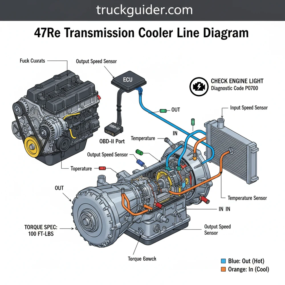
47RE Transmission Cooler Line Diagram: Setup Guide
The 47re transmission cooler line diagram identifies the flow from the front case port (outflow to the cooler) and the rear port (return inflow). Proper routing ensures fluid passes through the heat exchanger and auxiliary cooler, which is vital for the ECU to monitor temperatures and prevent overheating issues.
📌 Key Takeaways
- Identifies the supply and return paths for transmission fluid
- Locates the critical one-way check valve in the line
- Ensures lines are routed away from the exhaust to prevent fluid heating
- Helps prevent transmission failure caused by restricted fluid flow
- Used when replacing rusted lines or upgrading to an external cooler
Understanding the fluid circulation system of your heavy-duty transmission is essential for maintaining vehicle longevity and performance. If you are working on a Dodge or Ram truck equipped with the 4-speed automatic 47RE, you likely understand that heat is the primary enemy of your internal components. Finding an accurate 47re transmission cooler line diagram is a critical first step for any DIY mechanic or professional technician looking to perform repairs, upgrades, or routine maintenance. This article provides a comprehensive breakdown of the cooler line routing, identifying the supply and return ports, and offering technical insights into how the transmission manages thermal loads. You will learn how to identify each component, interpret the flow direction, and troubleshoot common issues that can lead to overheating or transmission failure.
The 47RE transmission uses a two-line system: a pressure line (hot) that sends fluid to the coolers and a return line (cold) that brings cooled fluid back to the rear of the transmission case. Proper identification of these lines is vital because the hot line often contains a check valve that is a frequent point of failure.
Comprehensive Breakdown of the 47RE Cooler Line Diagram
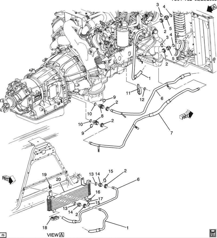
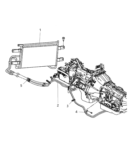
The 47RE transmission cooler line diagram illustrates a complex path designed to lower the temperature of the ATF+4 fluid before it recirculates through the planetary gears and clutch packs. On the transmission case itself, there are two main ports located on the passenger side. The front port, which is located closer to the bellhousing and the engine’s accessory belt area, is the “Out” or “Pressure” port. This is where the hot fluid exits the transmission. The rear port, located toward the tailshaft, is the “In” or “Return” port where the cooled fluid re-enters the system to lubricate the rear gear train.
The flow path typically involves two different cooling stages. First, the hot fluid travels from the front port to a liquid-to-liquid heat exchanger mounted on the side of the engine block. This exchanger uses the engine’s coolant flow to quickly bring the transmission fluid up to operating temperature in cold weather and shed excess heat into the radiator system during heavy use. From the heat exchanger, the fluid moves forward to the air-to-liquid cooler (the transmission radiator) located behind the grille. After passing through the cooling fins of the external radiator, the fluid travels back through a long metal and rubber line to the rear port of the transmission.
In the diagram, you will notice several key elements:
- ✓ The Hot Lead: Usually represented by a solid line originating from the front fitting of the transmission.
- ✓ The Check Valve: A small, cylindrical component integrated into the hot line, often near the heat exchanger connection.
- ✓ The Return Path: The line that connects the output of the front air cooler back to the rear transmission case fitting.
- ✓ Mounting Brackets: Points where the lines are secured to the engine block or frame to prevent vibration damage.
(Note: Imagine a schematic showing the transmission case with two ports. An arrow points from the front port toward a block-mounted exchanger, then to a front-mounted radiator, with a return arrow leading back to the rear port of the transmission.)
Step-by-Step Guide to Reading and Installing 47RE Cooler Lines
Interpreting a 47re transmission cooler line diagram requires a methodical approach to ensure the fluid flows in the correct direction. Reversing these lines can lead to immediate overheating and may trigger a check engine light if the internal thermistors detect an irrational temperature spread. Follow these steps to correctly identify and work with your cooler lines.
Step 1: Locate the Ports on the Transmission Case
Clean the passenger side of the transmission case with a degreaser. Identify the two brass or steel fittings. Remember the golden rule for the 47RE: Front is Out (Hot), Rear is In (Cold). The front port is under high pressure as it is fed directly by the oil pump.
Step 2: Trace the Line to the Heat Exchanger
Follow the line from the front port toward the engine block. It will lead to a cylindrical canister where the transmission fluid and engine coolant exchange heat. This area is often crowded by the accessory belt and various brackets. Ensure the line is not rubbing against any moving parts or sharp edges.
Step 3: Identify the Check Valve
While tracing the hot line, look for a slightly thicker section of the line with a hex-shaped fitting. This is the check valve. Its purpose is to prevent fluid from draining out of the torque converter when the vehicle is parked. However, it is a common restriction point. Many technicians use the diagram to identify this part for removal or replacement if a diagnostic code indicates poor flow.
Step 4: Connect to the External Air Cooler
The line exiting the heat exchanger (or the hot line if the exchanger is bypassed) travels to the top or side of the transmission cooler located in front of the engine radiator. Ensure you use a flare nut wrench to avoid stripping the soft metal fittings.
Step 5: Route the Return Line
The return line exits the other side of the air cooler. It must be routed carefully along the frame rail. Use the 47re transmission cooler line diagram to ensure you are using the correct clips and stand-offs. This line must remain clear of the timing chain cover and the exhaust manifold to prevent re-heating the cooled fluid.
Step 6: Secure and Torque the Fittings
Once the lines are routed, hand-thread the fittings into the transmission case to avoid cross-threading. Use a torque wrench to meet the specific torque spec for your year, typically ranging between 18 and 22 foot-pounds for the case fittings. Over-tightening can crack the transmission case, which is a catastrophic failure.
Step 7: Fluid Level and Leak Check
After installation, fill the transmission with ATF+4. Start the engine and cycle through the gears. While the engine is running, check every connection point identified in your diagram for leaks.
If you are replacing old, rusty lines, consider upgrading to high-pressure braided stainless steel lines. These bypass the common leak points at the factory “quick-connect” fittings and offer better heat dissipation. Always ensure the new lines follow the same routing path as shown in the original diagram to avoid interference with the steering linkage.
Common Issues and Troubleshooting the 47RE Cooling System
The 47RE transmission is relatively robust, but its cooling system has several known weak points. Using a 47re transmission cooler line diagram helps you isolate where a failure is occurring. One of the most common issues is a clogged check valve. When this valve becomes stuck with debris or clutch material, it restricts coolant flow, causing the transmission to overheat rapidly even under light loads.
If your vehicle triggers a check engine light, use an OBD-II scanner to pull the diagnostic code. Codes such as P0711 (Transmission Temp Sensor Range/Performance) or P0712 (Transmission Temp Sensor Low) often point to a flow issue rather than a sensor failure. If the fluid cannot reach the coolers due to a pinched line or a blocked heat exchanger, the ECU will detect the spike in temperature and may put the transmission into “Limp Mode” to prevent permanent damage.
Never ignore a transmission over-temp light. Unlike the engine coolant flow, which is managed by a thermostat, transmission fluid flows constantly while the pump is turning. A total blockage in the cooler lines can lead to a complete loss of lubrication to the rear bushings and planetary sets in minutes.
Another frequent problem is the “strawberry milkshake” condition. This occurs when the internal walls of the liquid-to-liquid heat exchanger fail, allowing engine coolant to mix with transmission fluid. This mixture is caustic to clutch material. If you see pink, foamy fluid on your dipstick, consult your diagram to locate the heat exchanger and bypass or replace it immediately.
Tips and Best Practices for Maintenance
Maintaining the 47RE cooling system involves more than just checking fluid levels. To ensure the system operates as the 47re transmission cooler line diagram intended, you should perform a flow test every time you service the transmission. To do this, disconnect the return line at the rear of the transmission and place it in a bucket. Start the engine briefly; you should see a strong, steady stream of fluid. If the flow is weak, you likely have a restriction in the coolers or the check valve.
Upgrade the Cooling Capacity
For those who tow heavy trailers, the factory air-to-liquid cooler may not be sufficient. You can use the diagram to identify the best points to “splice in” a larger aftermarket cooler. Always place the additional cooler in series with the existing system, ideally after the factory air cooler, to maximize temperature drop before the fluid returns to the case.
Monitor Torque Specs and Fitting Integrity
The vibration from the Cummins diesel engine (commonly paired with the 47RE) can loosen the cooler line fittings over time. During every oil change, perform a visual inspection of the lines near the accessory belt and the timing chain area. Ensure that the plastic clips are still intact. If a line is vibrating against the frame, it will eventually thin out and burst under pressure.
Use Quality Components
When replacing lines, avoid “universal” rubber hoses secured with worm-gear clamps. The 47RE pump can generate pressures exceeding 100 PSI in certain conditions, which can easily blow a hose off a smooth barb. Use flare fittings or specialized transmission compression fittings that meet or exceed OEM specifications.
The Role of the ECU and OBD-II in Thermal Management
Modern vehicles rely on the ECU (Engine Control Unit) to monitor the health of the 47RE. The transmission temperature sensor is located inside the governor pressure transducer. This sensor sends data to the ECU, which then manages shift points and torque converter lock-up based on fluid temperature. If the 47re transmission cooler line diagram is followed correctly and flow is optimal, the ECU should see temperatures between 150°F and 180°F.
If you encounter a diagnostic code related to transmission temperature, the first thing to check is the physical state of the cooler lines. A line that is bent or kinked during a different repair—such as a timing chain service or an accessory belt replacement—can cause an “irrational” signal to the ECU. The OBD-II system is excellent at telling you that a problem exists, but the 47re transmission cooler line diagram is what tells you where the physical problem is located.
Conclusion
Mastering the 47re transmission cooler line diagram is a fundamental skill for anyone dedicated to the upkeep of a Dodge or Ram vehicle. By understanding that the front port is the pressure outlet and the rear port is the return, you can effectively manage the cooling cycle of your ATF+4 fluid. Whether you are troubleshooting a check engine light, replacing a clogged check valve, or installing a high-performance heat exchanger, the routing of these lines is the lifeline of your transmission.
Proper maintenance, including checking for leaks at the fittings and ensuring that the lines are shielded from moving parts like the accessory belt, will prevent the most common causes of 47RE failure. Remember to always use a flare wrench, respect the torque specs of the brass fittings, and monitor your OBD-II data if you suspect a cooling issue. With the right diagram and a methodical approach to installation, you can ensure your 47RE transmission stays cool, even under the heaviest of loads. This proactive approach to cooling system management not only saves you thousands in repair costs but also ensures your truck remains a reliable workhorse for years to come.
Frequently Asked Questions
Where is the 47RE cooler line located?
The cooler lines are located on the passenger side of the transmission case. The front fitting is the pressure outlet sending hot fluid to the cooler, while the rear fitting is the return inlet. These lines run forward along the engine block toward the radiator and auxiliary cooling unit.
What does the 47RE cooler line diagram show?
This diagram illustrates the specific path transmission fluid takes from the 47RE case through the external cooling system. it highlights the connections between the transmission ports, the heat exchanger on the engine block, and the front-mounted air-to-oil cooler, ensuring no lines are crossed during a repair or installation.
How many connections does the 47RE cooler system have?
The system typically has four main hard-line connections at the transmission and cooler, plus additional union points depending on the specific vehicle model. It involves a supply line, a return line, and often bypass or check valve fittings that must be torqued precisely to prevent high-pressure fluid leaks during operation.
What are the symptoms of a bad cooler line?
Common symptoms include visible red fluid leaks, transmission slipping, or an illuminated check engine light. If the ECU detects high temperatures due to a restricted line, it may trigger a diagnostic code like P0218 via the OBD-II port, signaling that the transmission is operating in a dangerous overheat condition.
Can I replace the 47RE cooler lines myself?
Yes, a DIY replacement is feasible with basic hand tools and patience. The most difficult part is maneuvering the rigid hard lines around the engine bay. Ensure you have a catch pan ready for fluid and always double-check for leaks at the fittings after the vehicle has reached operating temperature.
What tools do I need for line replacement?
You will need a set of line wrenches (flare nut wrenches) to prevent rounding off the fittings, a drain pan, and potentially a quick-disconnect tool for certain factory clips. A torque wrench is also recommended to ensure every fitting meets the manufacturer torque spec, preventing stripped threads or leaks.

![Non Mds Lifters 5.7 Hemi Conversion [2026]](https://truckguider.com/wp-content/uploads/2026/03/featured-77288e71-768x768.webp)
![2022 RAM 2500 Fender Flares: Top Styles & Fitment Guide [2026]](https://truckguider.com/wp-content/uploads/2026/03/2022-ram-2500-fender-flares-featured.webp)