5.7 Hemi Timing Cover Bolt Diagram: Easy Setup Guide
A 5.7 Hemi timing cover bolt diagram shows the precise layout of approximately 10 to 14 fasteners that secure the front engine cover. This system configuration uses specific bolt lengths and studs to mount both the cover and water pump, ensuring a tight seal for the oil and cooling passages within the block.
📌 Key Takeaways
- Main purpose of this diagram is to ensure correct bolt length placement to prevent block damage
- Most important component to identify is the variety of bolt lengths and stud locations
- Critical consideration: over-torquing can crack the aluminum cover or strip the engine block
- Practical application tip: use a piece of cardboard to map out the bolt structure during removal
- When to use this diagram: during water pump replacement or timing chain maintenance
When embarking on a significant engine repair or maintenance task, such as a water pump replacement, timing chain service, or front main seal repair, having a precise 5.7 hemi timing cover bolt diagram is absolutely essential. The 5.7L Hemi engine, a staple of modern American muscle and utility, features a complex front engine configuration where bolt length and placement are critical to the integrity of the cooling and lubrication systems. Using the wrong bolt in the wrong hole can lead to catastrophic failures, including cracked engine blocks, stripped threads, or persistent coolant leaks. This comprehensive guide provides a detailed overview of the timing cover layout, offering a clear schematic to ensure your project is completed with professional accuracy and safety. You will learn how to identify each component, interpret the structural blueprint of the front assembly, and apply the correct torque specifications to maintain a leak-free system.
The 5.7 Hemi uses a combination of bolts and studs of varying lengths. Because the timing cover also serves as the housing for the water pump, several bolts pass through multiple components before reaching the engine block. Always keep track of which bolt came from which hole.
The primary 5.7 hemi timing cover bolt diagram serves as a visual map for the approximately 10 to 12 fasteners that secure the aluminum cover to the cast-iron engine block. The layout is somewhat asymmetrical to accommodate the water pump’s scroll and the various accessory drive brackets, such as those for the alternator, power steering pump, and air conditioning compressor. In a standard configuration, you will encounter two distinct sizes of fasteners: M6 and M8 bolts. The M6 bolts typically require a 10mm socket, while the larger M8 bolts and studs usually require a 13mm or 15mm socket.
Understanding the diagram requires looking at the cover as a clock face. The top-most bolts often double as mounting points for the water pump, while the bottom-most bolts are shorter and sit just above the oil pan interface. A key element of the schematic is the distinction between standard bolts and “double-ended” studs. These studs secure the timing cover but also provide a threaded extension for mounting wiring harness clips or accessory brackets. If you are working on a newer “Eagle” version of the 5.7 Hemi (typically found in vehicles produced after certain mid-generation updates), the blueprint may also show a specific port for the Variable Valve Timing (VVT) solenoid, which adds another layer of complexity to the layout.
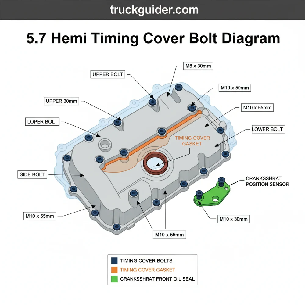
(Visual Description: A front-view schematic of the 5.7 Hemi engine block with the timing cover highlighted. Numbered circles 1 through 12 indicate bolt locations. Blue circles represent M6 bolts, red circles represent M8 bolts, and yellow circles indicate studs for brackets. A color-coded legend on the side correlates numbers to specific lengths in millimeters.)
The structural overview of the timing cover also includes the integration of the front crankshaft seal. This seal is pressed into the center of the cover and must be perfectly centered to prevent oil leaks. When viewing the layout, you will notice that the bolts surrounding the crankshaft are spaced evenly to provide uniform pressure on the gasket. This layout ensures that the mechanical stresses of the rotating assembly do not warp the aluminum cover over time.
To successfully interpret and use the 5.7 hemi timing cover bolt diagram, you must approach the task systematically. Following a structured layout helps prevent the “extra bolt” syndrome that plagues many DIY mechanics.
- ✓ 1/2-inch and 3/8-inch drive torque wrenches
- ✓ Metric socket set (10mm, 13mm, 15mm)
- ✓ Cardboard for a bolt template
- ✓ New timing cover gasket and RTV silicone sealant
- ✓ Harmonic balancer puller tool
1. Create a Physical Template: Before removing any fasteners, draw a rough outline of the timing cover on a piece of cardboard. As you remove each bolt according to the schematic, poke it through the cardboard in its corresponding position. This is the most effective way to ensure that a 100mm bolt doesn’t accidentally end up in a hole designed for a 65mm bolt.
2. Clean the Mounting Surfaces: Once the cover is removed, use a plastic scraper to remove all old gasket material and RTV from the engine block and the cover. A clean surface is paramount for a proper seal. Avoid using metal scrapers on the aluminum cover, as gouges will create leak paths.
3. Install the Crankshaft Seal: If you are replacing the front main seal, do so while the cover is off the vehicle. Use a seal driver tool to ensure it sits flush. The diagram indicates that the seal is the central focal point of the lower half of the cover.
4. Apply Sealant Correctly: Refer to your layout for the “T-junctions” where the engine block, cylinder head, and oil pan meet. You must apply a small bead of RTV silicone at these specific intersection points before laying the gasket down.
5. Hand-Thread All Bolts: Following your 5.7 hemi timing cover bolt diagram, place every bolt and stud back into its original hole by hand. Thread them in at least five full turns to ensure no cross-threading occurs. The various lengths are specifically engineered to accommodate the depth of the water pump and the thickness of the aluminum casting.
6. Execute the Torque Sequence: Tightening the bolts in a random order can warp the cover. Start from the center bolts and work your way outward in a “criss-cross” or “star” pattern. This ensures the gasket is compressed evenly across the entire surface area.
7. Verify Final Specifications: For most 5.7 Hemi engines, the M8 bolts should be torqued to approximately 21 ft-lbs (28 Nm), while the smaller M6 bolts require only about 9 ft-lbs (12 Nm). Refer to your specific vehicle’s service manual to confirm these numbers, as they can vary slightly by application.
8. Reinstall Accessories: Once the cover is secured, use the studs identified in your configuration overview to reattach the alternator and power steering brackets. These studs are often overlooked but are vital for the alignment of the serpentine belt system.
Never use an impact wrench to install timing cover bolts. The aluminum threads in the block or the cover itself are easily stripped, which may require a costly Time-Sert or Helicoil repair. Always use a calibrated torque wrench for the final pass.
Even with a detailed system overview, technicians often encounter hurdles during the assembly process. One of the most frequent issues is the “bottoming out” of a bolt. This happens when a long bolt is placed in a shallow hole. If you feel resistance before the bolt head meets the cover, stop immediately. Forcing it will either snap the bolt or crack the internal casting of the block.
Another common problem identified through the use of a diagram is the presence of galvanic corrosion. Because the bolts are steel and the cover is aluminum, moisture can cause the two metals to “weld” together over time. If a bolt feels spongy or extremely difficult to turn during removal, use a high-quality penetrating oil and apply heat if necessary. The blueprint helps you locate exactly where these stubborn fasteners are hidden, such as those tucked behind the harmonic balancer or the water pump pulley.
Signs of a failing timing cover seal or improper bolt installation include visible oil or coolant tracks running down the front of the oil pan. If you notice a “milky” appearance in your oil or a loss of coolant without a visible external leak, the internal gasket between the water pump and the timing cover may have failed. Consulting the diagram can help you determine if the leak is coming from a specific bolt hole that serves as a coolant passage, which is common in the 5.7 Hemi architecture.
When reinstalling the bolts, apply a small amount of anti-seize lubricant to the threads of the bolts that pass through coolant passages. This prevents future corrosion and makes the next disassembly much easier. However, reduce your torque values by about 10% to account for the lubrication.
To ensure the longevity of your engine, consider replacing the entire timing cover bolt set if the original fasteners show signs of significant rust or rounded heads. High-quality grade 8.8 or 10.9 steel replacements are recommended. Additionally, while you have the timing cover removed, it is the perfect time to inspect the timing chain tensioner and the oil pump. The 5.7 Hemi system is known for tensioner wear in high-mileage vehicles, and the cost of the part is negligible compared to the labor of removing the cover a second time.
Maintenance of the front engine configuration also involves checking the harmonic balancer. The rubber isolator in the balancer can degrade, causing the pulley to wobble. This wobble puts uneven stress on the timing cover and its fasteners, eventually leading to leaks or bolt fatigue. Ensuring the balancer is installed to the correct depth (often requiring a specific installation tool, not just the center bolt) is a critical step in the overall blueprint of the repair.
Cost-saving advice for DIY enthusiasts often centers on the “while you’re in there” philosophy. Replacing the water pump, thermostat, and serpentine belt simultaneously with the timing cover gasket can save hundreds of dollars in future labor. By using the 5.7 hemi timing cover bolt diagram as your primary guide, you reduce the risk of errors that lead to expensive professional corrections.
The importance of the 5.7 hemi timing cover bolt diagram cannot be overstated for anyone performing serious engine work. This schematic is more than just a list of locations; it is a structural overview that maintains the delicate balance between the engine’s cooling and lubrication systems. By understanding the configuration and following a precise installation sequence, you ensure that the aluminum housing remains perfectly flat and the internal gaskets are compressed to their design specifications.
Whether you are a seasoned mechanic or a dedicated DIYer, respecting the layout of the M6 and M8 fasteners will prevent the most common pitfalls of Hemi engine repair. Always prioritize cleanliness, use the cardboard template trick to organize your hardware, and never skip the final torque check. With the right blueprint in hand and a methodical approach to the task, your 5.7 Hemi will continue to provide the reliable power and performance it was engineered to deliver for years to come. Proper attention to the details of the timing cover assembly is the hallmark of a high-quality repair that stands the test of time and high-mileage driving conditions.
Step-by-Step Guide to Understanding the 5.7 Hemi Timing Cover Bolt Diagram: Easy Setup Guide
Identify – Start with identifying each bolt size and type using the diagram to prepare your workspace.
Locate – Locate the specific mounting studs that hold accessories like the alternator bracket or wiring harnesses.
Understand – Understand how the different bolt lengths correlate to the depth of the engine block holes to avoid bottoming out.
Apply – Apply a thin bead of RTV sealant to the corners of the cover where it meets the oil pan.
Verify – Verify that every bolt is placed in its correct position according to the diagram before tightening.
Complete – Complete the installation by torquing all bolts in a crisscross pattern to the manufacturer’s specified foot-pounds.
Frequently Asked Questions
Where is the 5.7 Hemi timing cover located?
The timing cover is located at the very front of the engine block, behind the water pump and harmonic balancer. It encloses the timing chain, sprockets, and oil pump drive. You must remove the cooling fan, shroud, and serpentine belt system to access this specific component layout.
What does the 5.7 Hemi timing cover bolt diagram show?
The diagram illustrates the specific bolt pattern, including which holes require long bolts, short bolts, or mounting studs. It clarifies the system configuration by showing which fasteners pass through the water pump and which secure the cover directly to the engine block for a leak-proof seal.
How many bolts are in the 5.7 Hemi timing cover system?
The typical 5.7 Hemi setup uses approximately 10 to 14 fasteners. This includes a mix of standard bolts and double-ended studs that serve as mounting points for accessories. Because lengths vary significantly across the cover structure, following a diagram is essential to avoid using a long bolt in a shallow hole.
What are the symptoms of a bad timing cover seal?
Symptoms include visible oil leaks from the front of the engine or coolant seeping from the water pump mating surfaces. If the bolt configuration is loose or the gasket has failed, you may notice puddles under the vehicle or a drop in fluid levels within the cooling system.
Can I replace the timing cover bolts myself?
Yes, this is a manageable DIY task for those with moderate mechanical experience. Using a proper diagram ensures you maintain the correct structure during reassembly. It requires basic hand tools, though a calibrated torque wrench is vital to prevent damaging the aluminum cover or the engine block threads.
What tools do I need for this task?
You will need a socket set (typically 10mm, 13mm, and 15mm), a torque wrench, a gasket scraper, and RTV silicone sealant. A harmonic balancer puller is also required to remove the crank pulley before you can access the full bolt layout of the timing cover system.