6.0 Powerstroke Sensor Location Diagram for 2003 to 2007

The 6.0 Powerstroke sensor location diagram starts with four areas: the engine valley, the intake system, the front engine cover, and the sides of the block. On 2003–2007 Ford Super Duty trucks, sensors in these areas monitor injection-control oil pressure, boost, exhaust pressure, temperature, and engine speed.
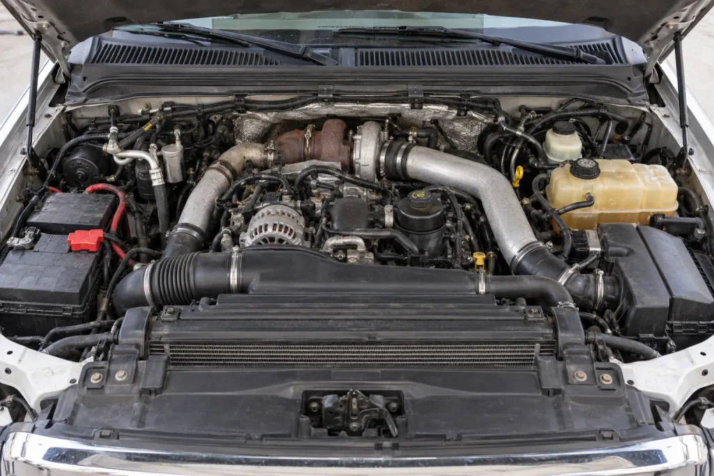
The key year-specific difference is the injection control pressure (ICP) sensor. Early engines place it behind the turbocharger; later engines place it near the passenger-side valve cover. Verify the configuration before ordering parts.
TruckGuider | 2003–2007 Ford Super Duty
6.0L Power Stroke Sensor Location Map
Quick-find engine areas and the critical early-versus-late ICP change. Location zones are schematic, not to scale.
Find the sensor by engine area
Driver side / left
Top / front engine
Passenger side / right
ICP Sensor: Two Different Locations
Verify 2004 engine configurationRear HPOP cover, behind turbocharger
Near the IPR regulator valve, beneath the turbo up-pipe collector.
Passenger-side valve-cover area
Near the glow-plug control module, at the right-front oil-rail location.
Do not mix them up: ICP measures pressure; IPR regulates pressure. Determine the actual 2004 configuration by physical location.
Identify the correct part in four checks
6.0 Powerstroke Sensor Location Diagram by Engine View
Recommended Best Deal Products


Use this location chart as a text-based map of the 6.0L Power Stroke V8. Left means driver side, and right means passenger side, following Ford service-manual orientation on U.S.-market Super Duty trucks. Front means the radiator end; rear means the firewall end.
| Sensor or Component | Where to Look | Physical Landmark |
|---|---|---|
| ICP sensor | Rear engine valley on early engines; passenger-side valve-cover area on later engines | Turbocharger and HPOP cover, or right valve cover |
| MAP sensor | Passenger-side rear engine-bay area | Bracket above the heater core, with a small hose to the intake manifold |
| EBP or EP sensor | Front driver-side engine area | Thermostat and secondary fuel-filter region; rigid exhaust-pressure tube |
| EOT sensor | Top of the engine at the oil-filter and oil-cooler assembly | Oil-filter base |
| ECT sensor | Front of the engine | Thermostat housing and coolant passage |
| IAT2 sensor | Intake manifold | Manifold air-temperature sensor threaded into the intake |
| MAF and IAT1 | Fresh-air inlet duct | Air-intake piping after the air filter |
| CMP sensor | Front driver-side engine block | Area behind the power-steering-pump mounting assembly |
| CKP sensor | Front passenger-side engine block | Behind the A/C compressor |
| EOP switch | Upper engine near the oil-filter assembly | Oil-filter base and related oil passages |
A single overhead view cannot reveal every part. CMP and CKP sit low, while MAP is mounted remotely. Use side views for hidden components.
Ford’s 6.0L Power Stroke service manual identifies components from front, side, rear, and top perspectives.
The 2003 model year also included both 7.3L and 6.0L diesel Super Duty trucks. If the engine identity is uncertain, compare the Power Stroke specifications by model year before using a 6.0L diagram.
Where Is the 6.0 Powerstroke ICP Sensor Located
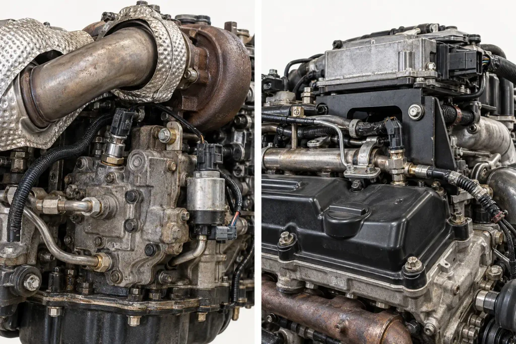
The ICP sensor moved during the 2004 production period. Early engines place it at the rear of the high-pressure oil system, beneath or behind the turbocharger. Later engines place it through the passenger-side valve-cover area, at the right-front high-pressure oil rail.
ICP means Injection Control Pressure. It measures the high-pressure engine oil operating the fuel injectors. The two locations require different access methods and parts.
ICP Location on Early Engines
On 2003 and early-build 2004 engines, look toward the firewall behind the turbocharger. The ICP sensor threads through the high-pressure oil pump (HPOP) cover, close to the injection pressure regulator (IPR) valve.
The turbocharger and exhaust up-pipe collector obstruct the view. ICP measures pressure; the adjacent IPR valve regulates it.
Turbo heat can damage the early ICP connector. Check for oil contamination or deteriorated wiring.
ICP Location on Later Engines
On late-build 2004 through 2007 engines, look along the passenger-side valve-cover area, near the glow plug control module. The sensor connects to the right-front high-pressure oil rail and is accessible without removing the valve cover.
Do not search beneath the turbocharger if the engine has the later arrangement.
For a 2004 truck, verify the engine build and physical mounting point. DieselHub’s early and late ICP reference documents both configurations.
Identification rule: Find the sensor’s mounting point before ordering an ICP sensor. A connector that fits a similar-looking part does not prove the part is correct for your engine.
Where Is the 6.0 Powerstroke MAP Sensor Located
Recommended Best Deal Products


The MAP sensor is mounted on a bracket above the passenger-side heater-core area, toward the rear of the engine compartment. It is not threaded directly into the 6.0L intake manifold.
A small hose connects the remote MAP sensor to a nipple on the intake manifold. Look for the hose and electrical connector.
Look above the passenger-side heater core, then trace the small hose to the manifold. The manifold nipple is not the sensor body.
MAP pressure includes atmospheric pressure. A scan tool’s MAP reading is therefore not the same as boost pressure shown on a gauge. With the key on and the engine off, MAP and barometric pressure readings should generally be close to one another, allowing for sensor tolerance and conditions.
A cracked, disconnected, pinched, or blocked MAP hose can create an inaccurate pressure reading even when the sensor works. Inspect the line before replacing the sensor. DieselHub’s 6.0L MAP sensor reference shows the mounting bracket and hose arrangement.
Where Is the 6.0 Powerstroke EBP Sensor Located
The exhaust back pressure (EBP) sensor, called the EP sensor in some Ford documentation, is identified by its rigid metal pressure tube. On the common 6.0L Super Duty layout, the sensor is near the front driver-side engine area, around the thermostat and upper fuel-filter region.
Follow the small metal tube upward from its connection at the exhaust manifold. The sensor has an electrical connector and receives pressure through the tube. Do not confuse it with the MAP sensor, which uses a rubber hose connected to the intake manifold.
EBP sensor and tube parts changed during production. Verify the actual tube routing before ordering a replacement.
Soot can restrict the exhaust-pressure tube and distort its readings. This is a reason to inspect the entire pressure path instead of assuming that a code or low-power complaint proves the electronic sensor has failed.
For broader EBP versus diesel particulate filter pressure-sensor identification, TruckGuider’s exhaust pressure sensor location guide explains the different pressure-sensing systems. The 2003–2007 6.0L Super Duty did not use the later factory DPF differential-pressure system.
Where Are the 6.0 Powerstroke Temperature Sensors Located
Recommended Best Deal Products


Three key readings are engine oil temperature (EOT), engine coolant temperature (ECT), and intake air temperature 2 (IAT2). Each measures a different location.
| Sensor | Main Location | What It Measures |
|---|---|---|
| EOT | Oil-filter base and oil-cooler housing area on top of the engine | Engine oil temperature |
| ECT | Front of the engine near the thermostat housing | Engine coolant temperature |
| IAT2 | Intake manifold | Air temperature entering the engine through the manifold |
| IAT1 | Air-intake piping after the air filter, associated with the MAF assembly | Incoming fresh-air temperature |
Engine Oil Temperature Sensor
The EOT sensor is in the upper oil-filter and oil-cooler housing area. Identify the large oil-filter cap first, then use the top-engine component view to distinguish the smaller temperature-sensor connection from adjacent oil-system components.
The EOT signal is especially useful when comparing oil and coolant temperatures with a suitable scan tool. An unusual difference between EOT and ECT readings requires diagnosis; it does not, by itself, prove that either sensor has failed.
Engine Coolant Temperature Sensor
The ECT sensor is at the front of the engine near the thermostat and related coolant passages. Do not confuse it with the EBP sensor, which can appear in the same general area but connects to a metal exhaust-pressure tube.
After a full cold soak, ECT and EOT should read reasonably close. Investigate a large discrepancy before condemning either sensor.
Intake Air Temperature Sensors
IAT2 measures intake-manifold air temperature and is installed in the intake manifold. IAT1 measures incoming air temperature in the fresh-air inlet path and is associated with the mass air flow (MAF) sensor arrangement after the air filter.
These are different measurement points. When inspecting an IAT2-related concern, follow the intake-manifold location rather than looking only at the air-filter duct.
How to Locate the CMP and CKP Sensors
CMP and CKP sensors sit low on the engine block and provide engine-position information for synchronization.
CMP Sensor Identification
The CMP sensor is on the front driver-side region of the engine block, behind the power-steering-pump mounting area. It is easier to understand its placement from the engine’s left-side component view than from an overhead engine-bay photograph.
Access may be easier through the driver-side wheel-well area, depending on the truck and installed components. Do not identify the sensor by following the fuel-injector harness. Look for the small sensor mounted into the block itself.
CKP Sensor Identification
The CKP sensor is on the passenger-side front of the engine block, behind the A/C compressor. Its lower mounting location makes it harder to see and reach than the CMP sensor.
If a scan tool reports camshaft or crankshaft position faults, confirm synchronization and wiring integrity before replacing components. A prolonged no-start event can produce both related codes without both sensors being defective.
How to Find a Suspect Sensor in 4 Steps
Use this four-step identification process before disconnecting anything or purchasing replacement parts. It works especially well when a scan tool identifies a system but not the physical component.
- Identify the exact engine. Confirm that the truck has the 6.0L Power Stroke rather than the 7.3L or 6.4L. On 2004 trucks, identify the early or late ICP arrangement by the actual mounting point. A 2003 Super Duty may require particular care because that model year included both 7.3L and 6.0L engines.
- Choose the correct engine view. Start with the sensor-location table. Use the top view for EOT, an engine-side view for CMP or CKP, the rear engine area for early ICP, and the passenger-side rear engine-bay area for MAP.
- Verify the physical landmark. With the engine off and cool, inspect the mounting point, electrical connector, and any related hose or tube. Never reach near a running fan or belt. Do not open the high-pressure oil system while the engine is operating or pressurized.
- Match identification with diagnostic evidence. Read diagnostic trouble codes (DTCs) and live parameter identifiers (PIDs) with a Ford-capable scanner. Follow the relevant service procedure. For an example of why codes require interpretation, see 6.0L Power Stroke diagnostic guidance.
Correct location does not establish that a sensor has failed.
Which 6.0 Powerstroke Components Are Not Sensors
Several nearby parts are routinely confused because they carry electrical connectors. Distinguishing a measuring device from a control component makes location diagrams more useful.
| Component | Common Confusion | Correct Identification |
|---|---|---|
| ICP sensor | IPR valve | ICP measures injection-control oil pressure |
| IPR valve | ICP sensor | IPR regulates high-pressure oil flow; it is an actuator |
| EOP switch | EOT sensor | EOP indicates oil-pressure-switch status; EOT reports temperature |
| MAP sensor | Manifold pressure nipple | MAP is the remote electrical sensor; the nipple is a hose connection |
| EBP sensor | DPF differential-pressure sensor | EBP uses a single exhaust-pressure tube on the 6.0L system |
| FICM | Engine sensor | FICM is the fuel injection control module |
| VGT control valve | Turbo speed sensor | The VGT control valve regulates turbo vane operation; it is not a speed sensor |
On early engines, ICP and IPR sit close together at the rear HPOP cover. On later engines, ICP moved.
For a comparison with the earlier diesel engine used in some 2003 trucks, TruckGuider also has a separate 7.3 Powerstroke sensor location diagram. Do not use that diagram to locate components on a 6.0L engine.
How to Verify Sensor Locations Before Repairs
A useful 6.0 Powerstroke sensor location diagram must match the actual engine, not merely the model year printed on the registration. Begin with the correct view, confirm the physical landmark, and identify the associated connector, hose, or pressure tube before handling the part.
The ICP change during 2004 is the clearest reason to verify the engine configuration first. The MAP sensor’s remote mounting and the EBP sensor’s metal tube are equally important visual clues. CMP and CKP require lower engine-side views rather than an overhead photograph.
Match replacement parts to the VIN and engine build. Use codes and live data to guide testing, not as proof of failure.
5 Common Questions About 6.0 Powerstroke Sensors
Where Is the ICP Sensor on a 2003 6.0 Powerstroke?
On a 2003 6.0L Power Stroke, the ICP sensor is at the rear of the engine, threaded into the HPOP cover beneath or behind the turbocharger. The IPR valve is nearby. If your 2003 Super Duty has the earlier 7.3L diesel instead, use the 7.3L engine-specific location reference.
Where Is the ICP Sensor on a 2005 6.0 Powerstroke?
On a 2005 6.0L Power Stroke, the ICP sensor is in the passenger-side valve-cover area at the right-front high-pressure oil rail. Look near the glow plug control module. This is the later arrangement, not the behind-the-turbo location used on early engines.
Where Is the MAP Sensor on a 6.0 Powerstroke?
The 6.0L MAP sensor is on a bracket above the passenger-side heater-core area. A small hose connects it to the intake manifold. If you see only the metal manifold nipple, follow the hose to reach the actual electrical sensor.
Are the EOT and ECT Sensors in the Same Location?
No. The EOT sensor measures engine oil temperature from the upper oil-filter and oil-cooler housing area, while ECT measures coolant temperature near the front thermostat housing. Their readings can be compared during diagnosis, but they are separate sensors in different locations.
Is the IPR Valve the Same as the ICP Sensor?
No. ICP is a sensor that reports injection-control oil pressure. IPR is a regulator valve that adjusts pressure in the high-pressure oil system. They are located close together on early engines, which is why the two components are sometimes confused.