6.4 Hemi Sensor Location Diagram: 2026 Ram 2500 and 3500

A 6.4 Hemi sensor location diagram helps identify the major engine sensors on Ram 2500 and 3500 trucks equipped with the 6.4L Hemi V8 gas engine.
The camshaft position sensor is at the front timing cover, while the crankshaft position sensor is mounted low on the right-rear side of the engine block in documented earlier Ram HD service references. Other sensors are mounted on the intake, cooling system, block, or exhaust.




Reference years matter. Use the map below, then check year-specific service information before replacing a sensor.
6.4 Hemi Sensor Location Quick Map


Find the correct engine area first. Sensor descriptions below are tied to documented service-reference years, not a universal 2014–2026 mounting diagram.
Top & Front of Engine
Start with hood openRight side of the front timing cover.
2015 service referenceRight-rear intake manifold (2016); upper intake near throttle body (2022).
2016 / 2022 referencesMounted in the air-intake tube.
2022 service referenceFront side of water-pump assembly.
2022 service referenceBlock & Lower Sides
Side or underside accessRight-rear cylinder block; generally viewed from below.
2016 service referenceRight block (2016); described as right-front engine (2022).
2016 / 2022 referencesOuter block, beneath the exhaust manifolds.
2015 service referenceExhaust & Underbody
Allow exhaust to coolIn exhaust flow before the relevant catalytic converter.
Verify bank and emissions packageIn exhaust flow after catalytic treatment, where equipped.
Sensor count varies by configurationThis is a location-reference infographic, not a scaled OEM placement drawing. Confirm the exact Ram model year, VIN, engine and emissions package before removing a component. Never inspect under a jack-only-supported truck or open a hot cooling system.
How to Read the 6.4 Hemi Sensor Location Diagram


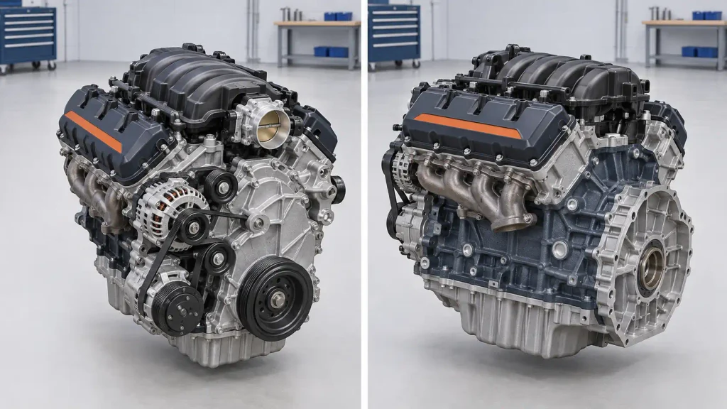
Read front as the radiator end of the engine and rear as the transmission or firewall end. Left and right refer to the truck’s sides when facing forward from the driver’s seat, not the sides of a photo taken from in front of the grille. On U.S. models, right means passenger side.
This table identifies major sensor regions, not a scaled or exhaustive engine drawing.
| Diagram Key | Sensor | Documented Mounting Area | Useful Viewing Direction |
|---|---|---|---|
| CMP | Camshaft position | Front timing cover, right side in 2015 service instructions | Front of engine |
| CKP | Crankshaft position | Right-rear cylinder block in 2016 instructions | From underneath |
| MAP | Manifold absolute pressure | Right-rear intake manifold in 2016; upper intake near throttle body in 2022 | Top of engine |
| IAT | Intake air temperature | Air intake tube in 2022 instructions | Upper intake tract |
| EOP | Engine oil pressure | Right side of block in 2016; right-front engine in 2022 description | Right/front of engine |
| ECT | Engine coolant temperature | Front of water pump in 2022 instructions | Front of engine |
| KS | Knock sensors, two | Outer cylinder block below exhaust manifolds in 2015 instructions | Lower sides of engine |
| O2 | Oxygen sensors | Exhaust pipes around catalytic converters | From underneath |
Do not treat every line as a universal 2014–2026 location. Several entries are tied to specific service years. CKP, knock, and oxygen sensors also need side or underbody views.


Step 1 Identify Ram 2500 Engine Reference Points

First, confirm the truck has the 6.4L Hemi V8 gas engine. A Ram 2500 or 3500 equipped with the 6.7L Cummins Turbo Diesel uses different sensors and a different engine layout. Do not substitute Dodge performance-car diagrams.
- Park on level ground, switch the ignition off, and let the engine cool.
- Identify the front accessory drive and timing cover at the radiator end.
- Find the intake manifold at the top of the V8 and trace the air intake tube toward the throttle body.
- Locate the cylinder-block sides below the exhaust manifolds and the rear of the engine near the transmission.
These landmarks establish engine orientation. For wider engine context, see the Ram 2500 6.4 Hemi engine specifications. With orientation established, the two engine-position sensors are the next reference points.
Step 2 Find 6.4 Hemi Camshaft and Crankshaft Sensors


The camshaft position sensor (CMP) and crankshaft position sensor (CKP) provide timing information to the Powertrain Control Module (PCM). Their mounting points differ.


Camshaft Position Sensor Location
In 2015 Ram 3500 6.4L service instructions, the CMP sensor is mounted on the right side of the engine’s front timing cover. The connector has little locking-tab clearance; service instructions require removing the air cleaner.
From the radiator end, inspect the timing cover’s passenger-side area and identify the sensor connector.
A 2022 Ram 2500 description also places the CMP on the front timing cover. Access procedures still require year-specific confirmation.
Crankshaft Position Sensor Location
The 2016 Ram 3500 CKP service instructions place the CKP at the right-rear side of the cylinder block, secured in a machined opening by a mounting bolt. It is not beside the CMP at the front cover.
Access is generally from underneath. Never work beneath a jack-only-supported truck; use a lift or appropriately rated stands. A crank-related code alone does not prove sensor failure.


Step 3 Locate 6.4 Hemi MAP and Air Sensors



MAP measures manifold pressure; IAT measures incoming-air temperature. Neither should be confused with diesel-specific airflow components.
MAP Sensor Location


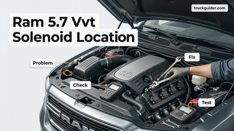
A 2016 Ram 3500 6.4L service procedure puts the manifold absolute pressure (MAP) sensor at the right rear of the intake manifold. The sensor is retained by a quarter-turn fitting and sealed by an O-ring.
A 2022 Ram 2500 MAP description describes the MAP as mounted to the upper intake manifold near the throttle body. For a 2022 truck, inspect the throttle-body area first and confirm against its service illustration.
Intake Air Temperature Sensor Location
For a 2022 Ram 2500 6.4L, the IAT sensor fits into the air intake tube. Its service procedure identifies a wiring connector and a twist-lock sensor body with an O-ring. Trace the intake tube and match its connector to the service illustration.
For a 2016 truck, verify the IAT location separately.
Mass Airflow Sensor Verification
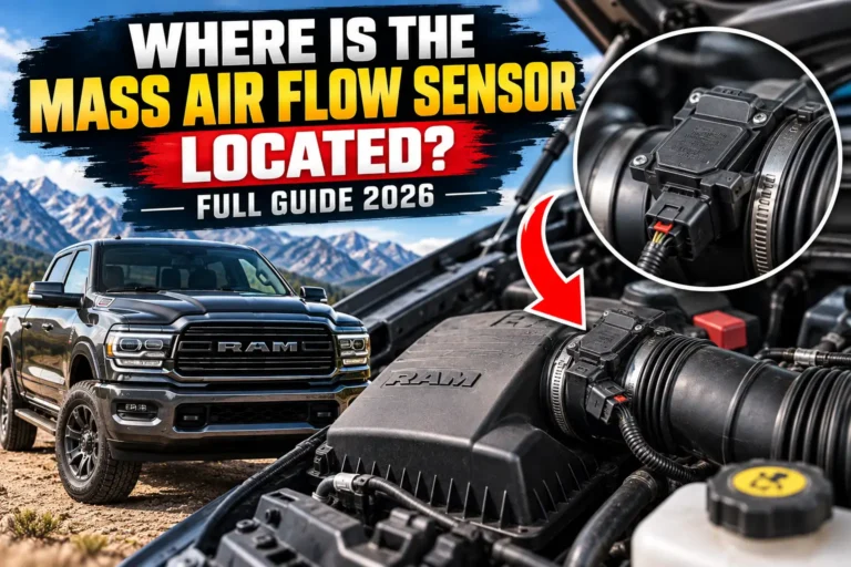
Do not assume a separate mass airflow (MAF) sensor belongs in every 6.4L Hemi diagram. Mixed-engine Ram parts catalogs also display 6.7L Cummins diesel air-mass sensors. Confirm the engine filter and part applicability before labeling or purchasing any MAF component for the gas V8.
Step 4 Identify 6.4 Hemi Oil and Coolant Sensors
Oil-pressure and coolant-temperature sensors have distinct mounting points.
Engine Oil Pressure Sensor Location
A 2016 Ram 2500 6.4L service description places the engine oil-pressure sensor on the right side of the engine block, threaded into the main oil gallery. A 2022 Ram 2500 description calls the position the right front of the engine. That wording does not establish a relocation.
Look in the right/front engine area on a 2022 truck. Do not confuse it with the separately listed oil-temperature sensor.
Engine Coolant Temperature Sensor Location


The 2022 Ram 2500 6.4L removal procedure identifies the engine coolant-temperature (ECT) sensor on the front side of the water pump assembly. A 2020 system description associates it with the thermostat-housing area. Use the 2022 water-pump reference for a 2022 truck rather than substituting a generic Hemi cooling diagram.
Safety: Do not remove the ECT sensor or open the cooling system while hot. Pressurized coolant can cause serious burns, and the service procedure requires partial draining before sensor removal.
For coolant routing, the 6.4 Hemi cooling system diagram provides related context. Match its illustration to your truck before using it to identify an individual sensor.
Step 5 Locate 6.4 Hemi Knock and Oxygen Sensors
Knock and oxygen sensors are better located from side and underbody views.
Knock Sensor Locations
The 2015 Ram 3500 6.4L instructions specify two knock sensors. Each bolts to the outside of the cylinder block below an exhaust manifold. Some installations include a sensor heat shield, making the sensor harder to recognize from above.
Look along the lower side of each cylinder bank, beneath the manifold area. Do not assume that any unmarked bolt or connector in that region is a knock sensor. Check the sensor, connector, and shield in the service diagram.
Upstream Oxygen Sensor Locations
Upstream oxygen sensors sit in the exhaust flow ahead of the relevant catalytic converter. A 2021 Ram 3500 6.4L reference describes one upstream sensor for each side, identified as 1/1 and 2/1. Use the actual exhaust routing to locate them.
Downstream Oxygen Sensor Locations
Downstream sensors monitor exhaust after catalytic treatment. A 2021 Ram 3500 6.4L reference describes four oxygen sensors overall, while 2016 service documentation distinguishes two-sensor federal configurations from four-sensor California configurations. Verify count and placement by year and emissions package.
Important: Exhaust pipes and converters stay hot after engine shutdown. Inspect from below only after cooling, using safe lifting equipment. Do not swap oxygen-sensor connectors based solely on cable length or a generic bank diagram.
Step 6 Match 6.4 Hemi Sensor Fault Codes
A diagnostic trouble code (DTC) indicates a condition, not a confirmed sensor failure. Wiring and mechanical faults can trigger similar codes.
The examples below come from the 2022 Ram 3500 6.4L diagnostic code index. Exact definitions and availability may vary by model year.
| DTC | Reported Circuit or Condition | Where to Start |
|---|---|---|
| P0335 | Crankshaft position sensor circuit | CKP and rear-block wiring |
| P0340 | Camshaft position sensor circuit | CMP and front timing-cover connector |
| P0107 / P0108 | MAP circuit low / high | MAP connector and reference circuit |
| P0112 / P0113 | IAT circuit low / high | Intake-tube temperature sensor |
| P0117 / P0118 | ECT circuit low / high | Water-pump or thermostat-area sensor |
| P0520 / P0521 | Oil-pressure sensor circuit / performance | Oil-pressure sensor and oil system |
| P0325 / P0330 | Knock sensor 1 / 2 circuits | Knock sensors and block-side wiring |
| P0131 / P0151 | Oxygen sensor 1/1 / 2/1 circuit low | Upstream exhaust sensors |
Record the complete code and freeze-frame information before clearing anything. Match the sensor name to the table, then inspect its connector and harness. A code involving oil pressure also calls for checking actual engine oil condition and pressure, not simply installing a new sensor. For related engine concerns, see common Ram 6.4 Hemi engine problems.
How to Verify 6.4 Hemi Locations by Model Year
The Ram HD 6.4L Hemi spans multiple model years, but a shared engine name does not prove that connectors, brackets, intake packaging, or exhaust equipment stayed identical. Published service descriptions are especially useful when they name the exact truck and engine.
| Model Years | Verified Reference Coverage | What to Confirm |
|---|---|---|
| 2014–2018 | Specific 2015–2018 Ram HD instructions identify major sensor areas | Engine option, sensor illustration, emissions package |
| 2019–2024 | 2020–2022 Ram HD descriptions identify later intake, cooling, and pressure-sensor areas | Exact year, VIN, engine and harness routing |
| 2025–2026 | No complete year-specific sensor-location set established for this reference | Current service information and VIN-filtered parts diagram |
These are research groupings, not verified redesign years. The documented 2016 and 2022 MAP descriptions differ in wording; that alone does not establish exactly when or whether the mounting position changed.
Use the Mopar parts catalog for 2022 Ram 2500 as a parts-identification starting point, then filter by VIN and the 6.4L gas engine. A diagram confirms a replacement only when the component and fitment match the truck.
How to Inspect 6.4 Hemi Sensors Before Replacement
Finding the sensor should lead to a controlled inspection, not an immediate purchase. These steps are suitable for initial identification; component removal and electrical tests require year-specific procedures.
- Verify the sensor. Compare its mounting area, body shape, and connector with a service reference for the exact truck.
- Read and record codes. Save active, pending, and stored DTCs along with relevant freeze-frame data.
- Inspect visible wiring. With the ignition off and engine cool, look for damaged insulation, unsecured connectors, corrosion, or heat exposure.
- Review live data. Compare applicable sensor values with expected conditions using a compatible scanner. Never conclude that a sensor is bad from one code alone.
- Confirm fitment and procedure. Check the replacement against the VIN and follow the correct safety, access, and post-repair verification instructions.
If you need a compatible tool, the Ram 2500 OBD2 scanner comparison covers diagnostic-tool options. For difficult access, damaged wiring, or uncertain test results, use a qualified technician instead of probing PCM pins or bypassing safeguards.
What to Check Next on Your Ram 6.4 Hemi
The 6.4 Hemi sensor location diagram is most useful when it matches the engine’s year and orientation. Start at the front timing cover for the CMP, the rear-right block for the CKP in documented earlier configurations, and the intake manifold for the MAP. The knock sensors belong below the exhaust manifolds, while oxygen sensors are part of the exhaust system.
Before removal, confirm the location using year-specific service information. Record codes, inspect wiring, and verify replacement fitment by VIN. If a connector is damaged or live readings conflict with the symptoms, follow the relevant circuit diagnostic test before buying a part. These checks reduce incorrect replacements and unnecessary disassembly.
Common 6.4 Hemi Sensor Location Questions
Where Is the Crankshaft Position Sensor on a 6.4 Hemi?


The CKP sensor is mounted at the right-rear side of the cylinder block in 2016 Ram 3500 6.4L service instructions. Access is generally from underneath the truck. Confirm the mounting point and safe access procedure for your exact model year before attempting removal.
Where Is the Camshaft Position Sensor on a 6.4 Hemi?
The CMP sensor is at the front timing cover. A 2015 Ram 3500 procedure specifies the right side of that cover and notes limited connector clearance. A 2022 Ram 2500 service description also identifies the front timing cover as its location.
Does the Ram 6.4 Hemi Have Two Knock Sensors?
Yes. The 2015 Ram 3500 6.4L service instructions describe two knock sensors mounted on the outside of the block below the exhaust manifolds. They can be obstructed by heat shields and nearby exhaust components, so use a side-view reference rather than guessing from above.
Where Is the MAP Sensor on a Ram 2500 6.4 Hemi?
The exact reference matters. A 2016 Ram 3500 description places the MAP at the right-rear intake manifold, while a 2022 Ram 2500 description places it on the upper intake near the throttle body. Use the service diagram for your year before ordering or removing the sensor.
Are 6.4 Hemi Sensor Locations the Same for All Model Years?
Not all locations can be confirmed as identical for every 2014–2026 Ram HD truck. Service references from different years describe certain areas differently, and exhaust equipment may vary. Verify the engine, VIN, emissions configuration, and relevant sensor illustration before performing work.