6.4 Powerstroke Sensor Location Diagram: Complete Guide 2026

The 6.4 Powerstroke sensor location diagram helps owners of 2008–2010 Ford Super Duty trucks identify engine and exhaust sensors without confusing one component for another.
On the 6.4L Power Stroke V8 diesel, the MAP and IAT2 sensors are on the intake manifold, the CKP is on the engine’s right side, the CMP is on its left, and the exhaust pressure sensor is at the left rear.

The fuel rail pressure sensor sits on the right high-pressure rail; the diesel particulate filter (DPF) pressure sensor is on the right frame rail. Identify the part before diagnosing a fault.
Start with the engine area, then confirm the mounting point in the model-year service diagram. This is a location-zone guide, not an exact-scale engine drawing.
Engine sensor areas
CMPCam position Left side of engine
EPExhaust pressure Left rear, near crossover plumbing
MAPManifold pressure Top intake manifold
IAT2Manifold air temperature Top intake manifold, near MAP
EOTOil temperature Oil filter base, upper engine
IAT1Intake air temperature Integrated into MAF, after air filter
CKPCrank position Right side of engine
FRPFuel rail pressure Right high-pressure rail, under valve cover
Front engine, near coolant-system components
Right frame rail in the factory 2008 Super Duty service locator
Factory exhaust temperature sensor order · flow direction →
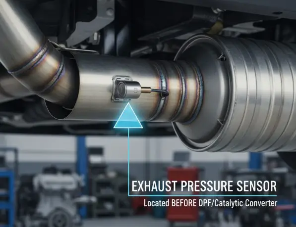
EP measures engine exhaust pressure before the turbo. The DPF pressure sensor monitors the aftertreatment system; these are different components.
Identification note: Engine left and right refer to the view from the driver’s seat. Do not loosen high-pressure fuel lines during sensor identification. Confirm year-specific connectors before repair.
6.4 Powerstroke Sensor Location Diagram by Engine View
Recommended Best Deal Products


Ford identifies engine sides from the driver’s seat: left is driver side; right is passenger side. The engine front faces the radiator.
This location table identifies engine areas, not exact mounting coordinates.
| View or Area | Sensors to Look For | Identifying Landmark |
|---|---|---|
| Front of engine | ECT | Front engine and coolant-system components |
| Left side | CMP | Left side of engine block |
| Left rear | EP or EBP | Area near turbocharger crossover plumbing |
| Right side | CKP | Right side of engine block |
| Right high-pressure fuel rail | FRP | Fuel rail beneath the right valve cover |
| Top intake manifold | MAP, IAT2 | Two separate intake-manifold sensors |
| Air intake duct | MAF with IAT1 | MAF housing downstream of the air filter |
| Top engine, oil filter base | EOT, EOP switch | Oil filter housing and oil cooler area |
| EGR cooler and turbo inlet | EGRT inlet and outlet | Rear turbo inlet and upper EGR cooler |
| Right frame rail | DPF pressure sensor | Bracket and pressure line near exhaust aftertreatment |
| Exhaust assembly | EGT11, EGT12, EGT13 | Before catalyst, between catalyst and DPF, after DPF |
Locations follow the Ford 6.4L Power Stroke technician guide, which illustrates front, side, rear, and top views. Confirm connector details against your model-year service manual.
Which Tools Help Identify 6.4 Powerstroke Sensors
Use a flashlight, inspection mirror, and Ford-capable scan tool. A phone camera can help reveal hidden connectors.
Park, shut off the engine, and let the exhaust cool. Follow vehicle-specific procedures before disconnecting electrical components.
Do not loosen high-pressure fuel lines or the FRP sensor for identification. Pressurized diesel fuel can cause serious injury. Use Ford’s service procedure before removal.
Where Are 6.4 Powerstroke MAP and IAT Sensors
The intake system has sensors that are often confused because their names and functions overlap. The MAP sensor measures manifold absolute pressure, while IAT sensors report air temperature at different points in the intake path.
MAP Sensor on the Intake Manifold
The manifold absolute pressure (MAP) sensor mounts directly in the intake manifold at the top of the engine. Find the cast intake manifold and use the Ford top-view illustration to distinguish the MAP sensor from the nearby IAT2 sensor.
MAP reads absolute pressure, not gauge boost. The boost pressure sensor and MAP guide explains the difference.
IAT1 Inside the MAF Assembly
Intake air temperature sensor 1 (IAT1) is integrated into the mass air flow (MAF) sensor assembly. The MAF/IAT1 assembly is in the fresh-air intake duct after the air filter, rather than mounted next to IAT2 in the manifold.
If a scan tool identifies an IAT1 circuit fault, begin at the MAF connector and intake-duct wiring. Do not substitute the nearby manifold temperature sensor.
IAT2 on the Intake Manifold
Intake air temperature sensor 2 (IAT2) is a separate sensor mounted in the intake manifold near MAP. It measures manifold air temperature after the air has passed through the turbocharging and charge-air-cooling path.
IAT1 and IAT2 readings can differ. Match the code’s sensor number before ordering parts.
Where Are 6.4 Powerstroke CKP and CMP Sensors
The engine uses two position signals for injection timing and cylinder identification. The crankshaft position (CKP) sensor and camshaft position (CMP) sensor are mounted on different sides of the engine.
CKP Sensor on the Right Side
Ford’s component locator places the CKP sensor on the right side of the engine. From the passenger side, follow the right-side engine view rather than searching around the upper intake manifold.
CKP supplies crankshaft position and speed data. With a related code, inspect the harness before replacing the sensor.
CMP Sensor on the Left Side
The CMP sensor is on the left side of the engine, as shown in Ford’s left-side component view. It identifies camshaft position so the engine controller can recognize cylinder timing in relation to the crankshaft signal.
CMP and CKP codes may involve wiring or synchronization, not necessarily failed sensors.
Where Are 6.4 Powerstroke ECT and EOT Sensors
The engine coolant temperature (ECT) sensor and engine oil temperature (EOT) sensor measure different fluids. Their locations are separate, so use the right engine landmark before checking a plug.
ECT Sensor at the Engine Front
Ford places the ECT sensor at the front of the engine. Use the front-facing component illustration and coolant-system components as landmarks, not an older 6.0L or 7.3L diagram.
Compare the scanner’s coolant-temperature reading with engine conditions. Never open a hot cooling system.
EOT Sensor at the Oil Filter Base
The EOT sensor is fitted to the oil filter base in the top engine area. Ford’s lubrication-system description identifies ports in the oil filter base for both the EOT sensor and the engine oil pressure (EOP) switch.
EOT reports temperature to the engine controller; EOP is a pressure switch for the dash gauge. Neither is an injection-control-pressure sensor.
Where Are 6.4 Powerstroke FRP and EP Sensors
Two pressure sensors that sound similar belong to different systems. FRP measures common-rail fuel pressure. EP, often called EBP, measures exhaust pressure before the turbocharger.
FRP Sensor on the Right Fuel Rail
The fuel rail pressure (FRP) sensor is fitted to the right-side high-pressure fuel rail, under the right valve cover. Ford’s fuel-system guide confirms this placement and explains how the control module uses FRP feedback to manage fuel pressure.
The right side is the passenger side when viewed from inside the truck. Do not confuse the FRP sensor with a low-pressure fuel supply component or fuel temperature sensor. Accessing the fuel rail requires a service procedure, not just removing a visible electrical connector.
EP Sensor at the Left Rear
The exhaust pressure (EP or EBP) sensor is at the left rear of the engine, near the turbocharger crossover area. Ford also identifies it in the left-side component view. It is connected to the exhaust-pressure sensing path, rather than measuring intake boost.
A blocked tube or damaged wiring can affect EP readings. EP is not the frame-mounted DPF pressure sensor.
Where Are 6.4 Powerstroke DPF and EGT Sensors
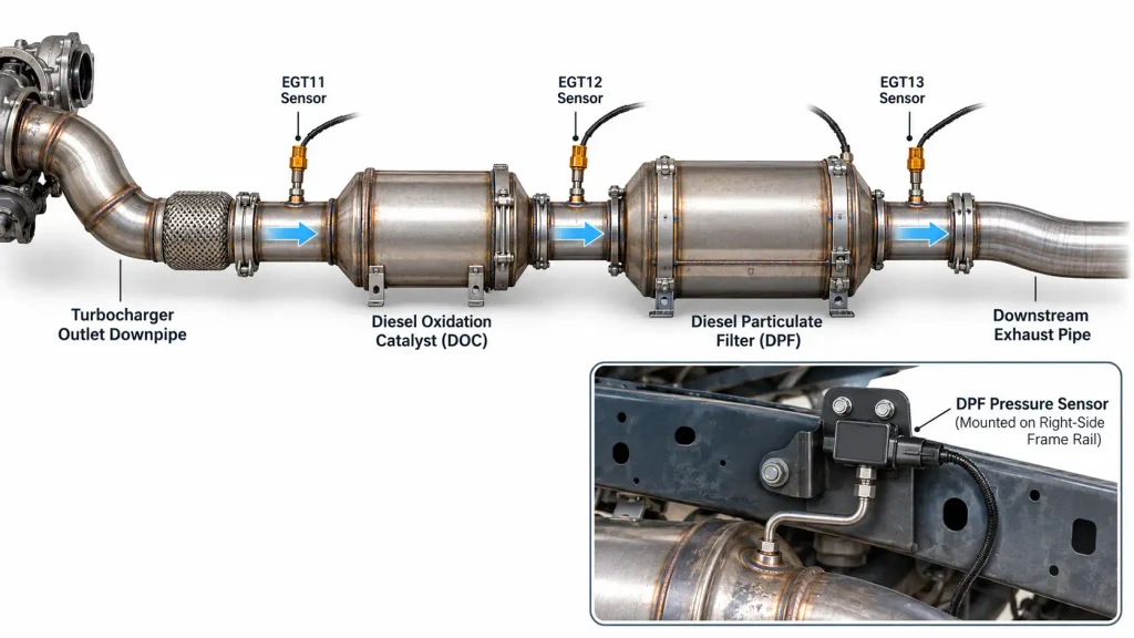
The factory exhaust aftertreatment system includes a diesel oxidation catalyst (DOC) and a diesel particulate filter (DPF). Its pressure and temperature sensors are installed away from the main engine-mounted sensor group.
DPF Pressure Sensor on the Frame Rail
On the 2008 Ford Super Duty 6.4L configuration, the DPF pressure sensor is mounted on the right frame rail. It monitors pressure associated with the exhaust aftertreatment system through a pressure connection.
Ford describes this sensor as a differential-type sensor referenced to atmospheric pressure. Do not assume it uses the same two-hose arrangement as every other diesel DPF sensor. A broader DPF pressure sensor location and symptoms guide compares systems found on other diesel engines; the 6.4L mounting location should still be checked against its own service diagram.
EGT Sensors Before and After the DPF
The factory system has three exhaust gas temperature (EGT) sensors along the exhaust after the turbocharger. Their numbering follows exhaust flow, not their apparent position from the side of the truck.
| Sensor | Location Along Factory Exhaust | What It Measures |
|---|---|---|
| EGT11 | Before the DOC | Exhaust temperature entering aftertreatment |
| EGT12 | Between the DOC and DPF | Temperature approaching the DPF |
| EGT13 | After the DPF | Exhaust temperature leaving the DPF |
Exhaust flow: Turbocharger outlet → EGT11 → DOC → EGT12 → DPF → EGT13 → downstream exhaust.
The EGR temperature (EGRT) sensors are different components. The EGRT inlet sensor is in the rear turbo-inlet/EGR gas path, while the EGRT outlet sensor is near the upper vertical EGR cooler. Do not mistake those engine-mounted probes for EGT11, EGT12, or EGT13 underneath the truck.
How to Identify 6.4 Powerstroke Sensors in 5 Steps
Use the same sequence whether you have a check-engine light or are identifying a part during routine inspection.
- Confirm the engine and year. Check that the truck uses the 2008–2010 6.4L Power Stroke V8. A 6.0L or 6.7L Power Stroke locator will not give you the correct component layout.
- Read and record the diagnostic code. Use a Ford-capable scan tool. Keep the exact code, its description, and available freeze-frame data instead of guessing from a symptom.
- Choose the correct viewing direction. Use the top view for MAP and IAT2, the side views for CKP and CMP, the left-rear view for EP, or the underbody view for DPF and EGT sensors.
- Match physical landmarks. Identify the intake manifold, oil filter base, valve cover, pressure tube, frame rail, or exhaust canister shown in the reference. Then confirm which electrical connector belongs to the sensor.
- Inspect before replacing. With the engine shut off and cool, check for an unplugged connector, damaged harness, corrosion, or an obviously restricted external pressure line. Use Ford’s circuit-testing procedure before replacing a sensor.
Confirm the sensor name, mounting point, and connector. A stored code does not prove sensor failure.
Which 6.4 Powerstroke Sensor Codes Need Attention
The Ford 2008 6.4L OBD system operation summary lists the following sensor-monitoring codes. They point to circuits or performance conditions that require diagnosis, not automatic replacement.
| Sensor or System | Example DTCs | What to Investigate First |
|---|---|---|
| MAP | P0106, P0107, P0108 | Manifold pressure signal and related wiring |
| IAT1 | P0112, P0113 | MAF/IAT1 assembly and connector |
| IAT2 | P0097, P0098 | Intake-manifold temperature sensor circuit |
| CKP | P0336, P0337 | Crankshaft position signal |
| CMP | P0341 | Camshaft position signal |
| ECT | P0117, P0118 | Coolant-temperature sensor circuit |
| EOT | P0197, P0198 | Oil-temperature sensor circuit |
| FRP | P0191, P0192, P0193 | High-pressure fuel rail feedback circuit |
| EP or EBP | P0472, P0473 | Exhaust-pressure sensor circuit |
| DPF pressure | P2452, P2453, P2454, P2455 | Aftertreatment pressure sensor and signal |
| EGT11 | P0545, P0546 | First aftertreatment temperature sensor circuit |
| EGT12 | P2032, P2033, P2084 | Middle temperature sensor and its signal |
| EGT13 | P242B, P242C, P242D | Downstream temperature sensor and its signal |
Circuit codes can indicate wiring or sensor faults; performance codes require broader checks. Compare model-year calibrations with Ford’s 2009 6.4L OBD documentation.
How to Avoid 6.4 Powerstroke Sensor Identification Mistakes
Mistake 1: Confusing MAP with IAT2. Both are on the intake manifold, but one measures pressure and the other temperature. Match the connector and sensor position to the Ford component drawing.
Mistake 2: Mixing up EP and DPF pressure. EP is at the left rear of the engine. The factory DPF pressure sensor is on the right frame rail. They monitor different parts of the exhaust system.
Mistake 3: Treating EOT as ICP. The 6.4L uses electronically controlled high-pressure common-rail injection. The 7.3L’s high-pressure-oil injection-control components do not carry over to this engine.
Mistake 4: Following an older Power Stroke diagram. The 7.3 Powerstroke sensor location diagram covers a different engine, including its ICP and IPR arrangement. It is useful for comparison, not for locating 6.4L parts.
Mistake 5: Replacing a part based on one code. Confirm the year, stored code, connector condition, and relevant live data. A fault associated with a sensor does not prove the sensor itself is defective.
Which 6.4 Powerstroke Sensor Should You Check First
The right starting point for a 6.4 Powerstroke sensor location diagram is the code or symptom you are investigating. Use the intake-manifold view for MAP and IAT2, the engine-side views for CKP and CMP, and the left-rear view for EP. Check the oil filter base for EOT and the right fuel rail for FRP.
For DPF pressure or EGT faults, move to the factory exhaust and right-frame-rail locations. Identify the correct component before working near hot exhaust parts or high-pressure fuel plumbing.
Once the sensor’s position is confirmed, inspect accessible wiring and compare scanner readings against Ford’s diagnostic procedure. That process reduces the chance of replacing a working component while leaving the real fault untouched.
5 Common Questions About 6.4 Powerstroke Sensors
Where Is the 6.4 Powerstroke MAP Sensor Located
The MAP sensor is mounted on the intake manifold at the top of the 6.4L Power Stroke engine. A separate IAT2 sensor is nearby, so compare both locations against the Ford top-view component diagram before disconnecting either one.
Where Is the 6.4 Powerstroke EBP Sensor
The exhaust backpressure sensor, identified by Ford as the EP sensor, is at the left rear of the engine. Look near the rear exhaust and turbocharger crossover area. It is not the DPF pressure sensor mounted on the frame rail.
Does the 6.4 Powerstroke Have an ICP Sensor
The 6.4L does not use the older 7.3L-style ICP sensor and IPR valve for hydraulic injector control. Its common-rail injection system uses the FRP sensor on the right high-pressure fuel rail, along with fuel-pressure control devices.
Are 2008 and 2010 Sensor Locations Identical
The 2008–2010 Ford Super Duty 6.4L trucks share the same engine family and principal sensor groups. However, use a VIN- or year-specific service reference for exact connector routing, component access, and emissions-equipment details before repair.
Where Is the 6.4 Powerstroke DPF Pressure Sensor
The factory DPF pressure sensor is mounted on the right frame rail on the documented 2008 Super Duty arrangement. Find the sensor bracket and its exhaust-pressure connection, rather than searching the intake manifold or the engine’s left-rear EP sensor location.