1998 Ford F150 Fuse Box Diagram: 2026 Troubleshooting Guide

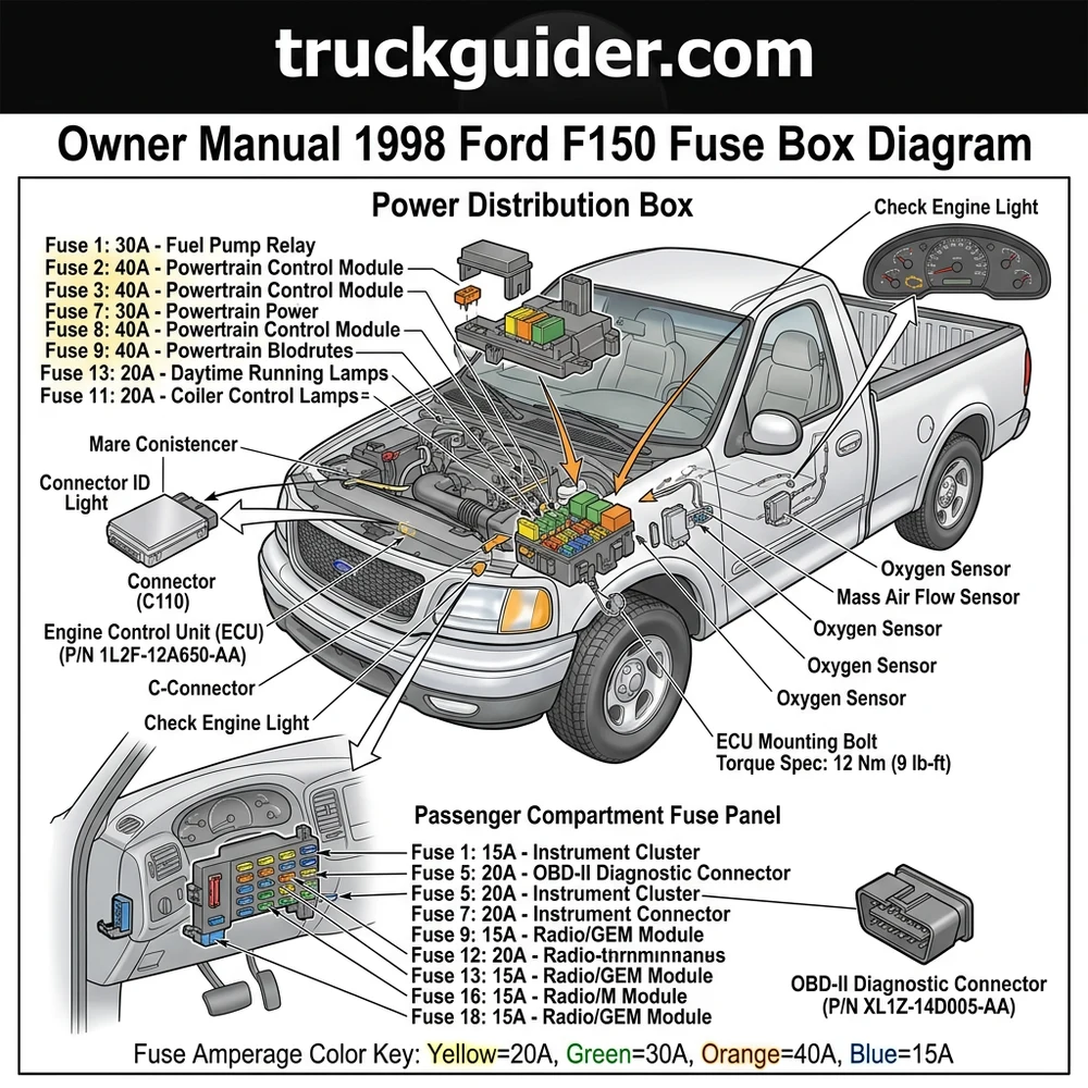
The 1998 Ford F150 features two primary fuse panels: the interior cabin panel on the driver-side dash end and the Power Distribution Box in the engine bay. The engine bay box houses critical high-amperage relays for the ECU, fuel pump, and PCM, typically labeled with specific amperage ratings ranging from 5A to 60A.
📌 Key Takeaways
- The interior panel controls cabin accessories, while the engine Power Distribution Box manages core ECU and powertrain circuits.
- Use a 12V test light or multimeter to verify voltage at fuse test points rather than relying on visual inspection.
- Maintain a standard torque spec of 8-10 Nm for any ground strap connections removed during electrical diagnostic procedures.
- The most common failure point is oxidation on the fuel pump relay pins, often leading to intermittent stalling or a no-start condition.
- Seek professional assistance if diagnostic code (DTC) scanners indicate a short-to-ground in the PCM harness, as this requires advanced electrical schematics.
The electrical architecture of the tenth-generation Ford F-150 relies on a robust dual-power center system to manage distribution to the Engine Control Unit (ECU), lighting, and cabin accessories. When diagnosing intermittent power loss or complex electrical faults, an accurate owner manual 1998 Ford F150 fuse box diagram is the primary tool for technicians. Understanding the interplay between the internal passenger compartment fuse panel and the high-amperage under-hood power distribution box is critical for isolating failures in circuits ranging from fuel pump relays to heated oxygen sensors. This guide provides the technical specifications required to interpret these diagrams, ensuring precise component identification for professional automotive repair and maintenance.
Component Identification: 1998 Ford F150 Power Centers


The 1998 Ford F-150 utilizes two distinct power management hubs. The first is the Power Distribution Box, located in the engine bay on the driver-side fender well. This module houses high-amperage maxi-fuses and various relay banks that control heavy-load components, including the starter solenoid, ignition system, and cooling fan relays. Unlike the cabin panel, these circuits are designed to manage high current flow and are susceptible to environmental corrosion given their exposure to the engine bay.
The second hub is the Instrument Panel Fuse Block, situated behind the removable access panel on the left side of the dashboard. This block manages low-amperage secondary circuits, such as the radio, interior lighting, cluster gauges, and OBD-II data port. Accessing this panel requires careful manipulation of the spring-loaded door clips.
Internal to these blocks are standardized blade-style fuses, color-coded by amperage. It is essential to recognize that the 1998 model year represents a transitional phase in the F-Series platform. While physically similar to the 1997 model, certain circuit arrangements—particularly those feeding the ECU and transmission solenoids—differ based on whether the vehicle is equipped with the 4.2L V6, 4.6L Triton V8, or 5.4L Triton V8.
Always verify the circuit load before swapping a fuse. Using a higher amperage rating than specified in the factory diagram can result in thermal damage to the wiring harness, potentially compromising the ECU or other sensitive electronic modules.
Relays within these boxes are often interchangeable by design, but they are not universal. Technicians should inspect the relay pins for pitting or carbon buildup, which can cause excessive resistance, leading to erratic performance in systems like the fuel pump or blower motor. Always match the OE part number on the relay housing to ensure correct pin configuration and internal switching capability.
How to Read the Owner Manual 1998 Ford F150 Fuse Box Diagram


Interpreting the official fuse map requires an understanding of your vehicle’s specific trim level and powertrain configuration. The owner manual 1998 Ford F150 fuse box diagram provides a numerical index that corresponds to the physical slots within the fuse blocks. When referencing these, note that slots labeled “spare” are not wired to any downstream component; they are provided solely for emergency replacements.
| Fuse/Relay ID | Circuit Function | Amperage/Spec |
|---|---|---|
| Fuse 1 | Powertrain Control Module (PCM) | 15A |
| Fuse 13 | OBD-II Port / Cigarette Lighter | 20A |
| Relay 3 | Fuel Pump Power | 40A Maxi |
| Fuse 19 | Instrument Cluster / ECU Data | 7.5A |
When cross-referencing, ensure the document covers the 1998 model year specifically. The F-Series platform underwent subtle revisions during the 1997-1998 rollout, specifically regarding the grounding paths for the ECU. Misidentifying a circuit could lead to an incorrect diagnostic conclusion when attempting to resolve a check engine light. Furthermore, factory manuals often list “optional” fuses that may not be populated in lower trim levels (e.g., XL vs. Lariat). If a fuse slot is present but the terminals are empty, the vehicle wiring harness for that specific option is likely absent, and installing a fuse will not activate the component.
Common Issues and Symptoms Requiring Fuse Inspection



Identifying electrical failures requires differentiating between a blown fuse and a deeper systemic issue. A fuse is a sacrificial device; if it blows, there is an underlying reason—typically a short circuit to ground or an over-current draw from a failing component.
ECU Communication Errors: If your scan tool cannot establish a handshake with the ECU, the fuse protecting the OBD-II diagnostic port or the PCM power relay is the primary suspect.
Intermittent Check Engine Light: Fluctuating voltage to sensors, such as the mass air flow or oxygen sensors, often originates from poor contact in the fuse block or a partially melted fuse holder.
Erratic Oil Pressure Gauge Readings: While often related to the sending unit, a loss of reference voltage through the instrument panel fuse block can cause the gauge to bottom out.
Coolant Flow Issues: If the cooling fan fails to engage, inspect the high-amperage relay in the engine bay distribution box. A burnt relay contact often prevents the necessary current flow for the fan motor.
* Timing Chain and Sensor Synchronization: In rare cases, a failing fuse powering the Crankshaft Position Sensor (CKP) can cause an open circuit, leading to a no-start condition that mimics timing chain slippage or catastrophic mechanical failure.
Always check for continuity across the fuse blades using a multimeter before assuming the component itself is functional. A visual inspection through the translucent plastic housing may occasionally miss a hairline fracture in the metal link.
Diagnostic Steps for the Owner Manual 1998 Ford F150 Fuse Box Diagram


Troubleshooting an electrical fault requires a methodical approach to prevent damage to the vehicle’s electronic infrastructure. Follow these steps when using your owner manual 1998 Ford F150 fuse box diagram to isolate a fault.
1. Verify the Diagnostic Code: Before touching the fuse box, connect a scanner to the OBD-II port. If a diagnostic code points to a specific circuit (e.g., P0135 for O2 sensor heater circuit), locate the corresponding fuse in the diagram.
2. Initial Inspection: Use a fuse puller tool to extract the suspected fuse. Examine the metallic element for signs of vaporized metal, which indicates a short circuit, or darkening of the plastic housing, which suggests localized overheating and resistance.
3. Test for Continuity: Set your multimeter to the resistance (Ohms) setting or the continuity buzzer. Place leads on both blades of the fuse. A reading of “OL” or no buzzer tone indicates an open circuit.
4. Check Voltage at the Block: If the fuse is intact, use a circuit tester or multimeter to check for 12V+ power on the supply side of the fuse socket with the ignition in the “Run” position.
5. Analyze Downstream Load: If the fuse keeps blowing, do not simply install a higher-rated fuse. This is a common error that can lead to vehicle fires. Instead, use a clamp meter to measure the amperage draw of the circuit while the system is under load. Compare this to the factory-rated current capacity.
6. Check Grounding Points: Frequently, a “blown fuse” symptom is actually a failure of a chassis ground point. Inspect the engine-to-chassis grounds and the ECU ground straps for corrosion.
Never bridge a fuse socket with wire or metal objects. This bypasses the safety mechanism entirely and exposes the vehicle’s wiring harness and expensive modules like the ECU to permanent damage from unregulated current spikes.
If you are performing major engine repairs, such as addressing timing chain wear or coolant flow restrictions, ensure you have documented all electrical connectors that were disconnected. Re-seating these with improper torque specs or failing to ensure a solid electrical connection at the sensor plug can manifest as a fuse-related failure. Always consult the OEM service manual for the correct torque spec for any hardware removed during your diagnostic process.
Owner Manual 1998 Ford F150 Fuse Box Diagram Questions Answered
Is it safe to use a fuse with higher amperage if the specified one keeps blowing?
No. You should never increase the fuse rating. A fuse is sized to protect the weakest link in the wire gauge of that specific circuit. Increasing the rating allows the wiring to reach temperatures that can melt the insulation and cause a short-circuit fire. Always find the source of the short.
Why does my scan tool indicate a “No Link” error despite a good fuse?
This usually indicates an open circuit in the diagnostic data line or a ground fault at the OBD-II port. Check the fuse for the cigarette lighter, as it often shares a power feed with the OBD-II port’s auxiliary power supply. Verify that your scanner is compatible with the Ford PWM (Pulse Width Modulation) communication protocol used in 1998 models.
Can a bad relay mimic a blown fuse?
Yes. A relay contains internal contacts that can become pitted or fail to close, effectively acting as an open circuit. If the fuse is intact, swap the suspected relay with an identical one from a non-critical circuit, such as the horn, to verify if the function is restored.
Does engine oil pressure affect the electrical system?
The oil pressure gauge is an electrical component, not a mechanical one in this model. If the gauge drops to zero, check for a blown instrument panel fuse or a disconnected wire at the oil pressure sender. A failure here is electrical in nature, not mechanical, though always verify actual oil pressure with a mechanical gauge if the low oil pressure warning lamp illuminates.
How do I identify if the Power Distribution Box has internal corrosion?
If multiple fuses in the engine bay box show signs of blue-green oxidation on the blades, moisture has breached the seal. Use an electrical contact cleaner and a small wire brush to clean the terminals. If the corrosion is severe or deep within the socket, the entire power distribution block may require replacement to prevent future continuity issues.
Step-by-Step Guide to Understanding the Owner Manual 1998 Ford F150 Fuse Box Diagram
Identify – Locate the fuse box cover and cross-reference the layout with your specific trim level’s diagram.
Locate – Find the specific fuse number linked to your malfunctioning component (e.g., fuel pump or ECU).
Reference – Use a multimeter to check for 12V power at the fuse top test points.
Connect/Route – Inspect wiring harness pins for signs of melting or loose connections if the fuse appears intact.
Verify – Insert a new fuse of the exact same amperage and observe for further blown components or diagnostic code changes.
Troubleshoot – If the issue persists, use an OBD-II scanner to monitor live data and isolate shorted sensors or faulty ground straps.