2001 Ford F150 Brake Line Diagram: Proper Routing & Repair (2026)

The 2001 Ford F150 brake line system utilizes a primary and secondary circuit originating from the master cylinder to the ABS hydraulic control unit (HCU). Lines travel along the driver-side frame rail. Critical torque spec for M10x1.0 inverted flare fittings is 15-18 ft-lbs to prevent leaks and ensure system integrity.
📌 Key Takeaways
- Use 3/16-inch double-flared steel tubing for all primary hydraulic line replacements.
- The HCU serves as the central hub; ensure line ports correspond to the correct master cylinder output.
- Standard flare nut torque is 15-18 ft-lbs; over-tightening can crack the brass fittings.
- Corrosion at frame clip points is the #1 failure mode due to road salt and moisture trapping.
- If a dashboard warning light or OBD-II ABS code persists, perform a system bleed using a scan tool to cycle the HCU valves.
Maintaining the hydraulic integrity of a 2001 Ford F150 is critical for vehicle safety and performance. Because these trucks often operate in demanding environments, the brake lines are susceptible to oxidation and structural fatigue. Understanding the 2001 Ford F150 brake line diagram is essential for any technician tasked with tracing leaks, performing a full system flush, or replacing corroded hard lines. Unlike modern vehicles that rely heavily on complex electronic stability control modules integrated with the ECU, the 2001 model utilizes a more mechanical hydraulic architecture, though it still interfaces with an ABS Hydraulic Control Unit. Proper identification of each line, fitting, and junction block ensures that your service procedures adhere to original equipment manufacturer (OEM) standards.
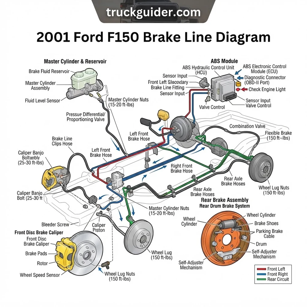
2001 Ford F150 Brake Line Diagram: Every Part Labeled
Recommended Best Deal Products


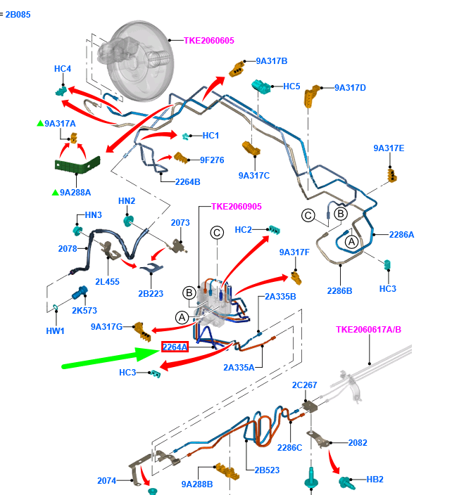
To effectively navigate the brake system, you must distinguish between the high-pressure steel lines and the flexible rubber hoses. The system begins at the master cylinder, where fluid is pressurized and directed toward the ABS Hydraulic Control Unit (HCU). In the 2001 Ford F150 brake line diagram, the HCU acts as the central hub for pressure modulation. From here, the fluid is routed through various steel hard lines toward the individual wheel cylinders or calipers. Accurate identification of these components is vital, especially when dealing with the rear brake proportioning valve on different chassis configurations.
| Component | Function | Material/Note |
|---|---|---|
| Master Cylinder | Pressure Generation | Aluminum Cast |
| ABS HCU | Pressure Modulation | Electronic Control |
| Hard Brake Lines | Fluid Transfer | Coated Steel |
| Proportioning Valve | Bias Adjustment | Chassis Mounted |
The hard lines are constructed from double-walled, brazed steel tubing, typically with a zinc coating to resist external corrosion. When utilizing the 2001 Ford F150 brake line diagram, pay close attention to the junctions at the frame rail. These areas are prone to debris accumulation and moisture trapment. Furthermore, while the ECU monitors sensor data through the OBD-II port, the actual modulation of brake pressure remains a hydraulic function managed by the HCU. Technicians should verify that lines are properly secured with clips to prevent vibration-induced fatigue. If you notice a check engine light or specific ABS diagnostic code, ensure the electrical harness to the HCU is not compromised before assuming a hydraulic failure.
Common 2001 Ford F150 Brake Line Diagram Issues and Symptoms

The primary concern with this generation of F150 is localized corrosion of the steel brake lines, particularly where the lines are secured by plastic or metal retaining clips. Over time, moisture becomes trapped between the clip and the line, causing aggressive exterior pitting. This degradation often manifests as a soft or spongy brake pedal, or in severe cases, total hydraulic failure. Unlike an oil pressure drop or a timing chain rattle, which might present as engine noise, brake line failure is often silent until the moment of crisis.
Do not attempt to repair heavily corroded brake lines by “patching” or using compression fittings. The 2001 Ford F150 brake line diagram indicates high-pressure zones that require double-flared, seamless steel or NiCopp lines to meet federal safety standards. Compression fittings are strictly forbidden for hydraulic brake applications due to blowout risk under panic-braking conditions.
Monitoring brake fluid levels is a primary preventative measure. If the fluid level drops without visible leakage at the calipers or wheel cylinders, the culprit is often a pinhole leak in one of the long runs of hard line along the chassis. Because the F150’s coolant flow system and engine cooling components are often serviced in the same engine bay proximity as the master cylinder, ensure that no coolant contamination has reached the brake reservoir. Brake fluid is hygroscopic; once it is contaminated with water or other fluids, the internal boiling point drops, significantly reducing the efficiency of the hydraulic system.
How to Diagnose the 2001 Ford F150 Brake Line System
Recommended Best Deal Products


Diagnostic procedures should be performed systematically to avoid “parts-swapping” syndrome. Follow these steps to verify your system integrity:
1. Visual Inspection: Inspect the entire length of the lines according to the 2001 Ford F150 brake line diagram. Use a mirror to look at the top side of the lines where they run along the frame rail. Look for signs of “weeping” or dark, wet residue.
2. Pressure Testing: Have an assistant depress the brake pedal firmly while you observe the lines. If you feel a “pulsing” or see a bulge in any flexible hose, the hose is internally failing. If you spot a spray, the steel line has reached its service limit.
3. ABS HCU Verification: If a diagnostic code indicates an HCU failure, verify the ground and power supply at the harness connector before condemning the unit. Occasionally, a bad ground can trigger an ABS warning light that mirrors a hydraulic leak symptom.
4. Proportioning Valve Check: Ensure that the valve is not stuck. If the front or rear brakes are locking up disproportionately, the internal seals within the proportioning valve may be bypassed, which is a common failure point for higher-mileage vehicles.
When scanning for errors via the OBD-II port, distinguish between “hard” and “soft” codes. A hard code related to the HCU usually points to a sensor or internal solenoid fault, whereas soft codes might be related to wheel speed sensor discrepancies. Always clear codes after major brake work to ensure the ECU recalibrates properly.
2001 Ford F150 Brake Line Diagram Replacement Standards
Replacing lines on an F150 requires adherence to strict torque specs and flare types. The 2001 model predominantly uses SAE inverted flares. Using the wrong flare type will lead to an immediate leak. When choosing replacement materials, many technicians opt for copper-nickel (NiCopp) lines because they are highly corrosion-resistant and easier to bend without kinking, unlike standard steel lines.
| Specification | Requirement |
|---|---|
| Flare Type | Double Inverted (SAE) |
| Line Diameter | 3/16″ or 1/4″ (varies by circuit) |
| Fitting Torque | 12-15 lb-ft (do not overtighten) |
| Fluid Type | DOT 3 Brake Fluid |
Always consider the differences between 2WD and 4WD configurations. The 4WD models feature different routing around the front drive axle and T-case, which can make the 2001 Ford F150 brake line diagram slightly different from the 2WD diagram. Failure to account for this can lead to lines rubbing against rotating assemblies, which results in catastrophic failure. When installing new lines, ensure they are secured in the OEM clips; if the original clips are missing, use stainless steel zip-ties to prevent vibration, but ensure they do not create a friction point.
2001 Ford F150 Brake Line Diagram Questions Answered
Recommended Best Deal Products


Is it possible to bend my own lines using the diagram?
Yes, but you require a high-quality tubing bender. Hand-bending often leads to “kinking,” which restricts fluid flow. A restricted line can cause a caliper to drag, leading to excessive heat buildup and potential premature oil pressure sensor warnings or general engine overheating due to extra load. Always practice on scrap tubing before bending the permanent lines.
Does the 2001 Ford F150 brake line diagram cover ABS components?
The diagram provides the routing to and from the ABS HCU. However, it does not include internal electronic wiring schematics for the ECU. If you are troubleshooting an ABS light, ensure you also consult your factory service manual for the wiring pinout, as the brake lines only represent the hydraulic portion of the system.
Why does my brake fluid turn dark so quickly?
Dark fluid indicates oxidation and the absorption of moisture. If you notice this repeatedly, check the master cylinder cap seal. If the seal is compromised, moisture enters the system constantly, leading to internal corrosion of the hard lines. This is a common issue that makes the 2001 Ford F150 brake line diagram relevant even for routine maintenance tasks like flushing.
Are there torque specs for the brake line fittings?
Yes, standard practice for these fittings is 12 to 15 lb-ft. Because the fittings are often steel and the HCU or proportioning valve body is aluminum, it is very easy to strip the threads. Use a line wrench (flare nut wrench) rather than an open-end wrench to avoid rounding off the hex heads on the fittings.
Always perform a complete system bleed using a two-person method or a vacuum bleeder after any line replacement. Starting from the wheel farthest from the master cylinder (typically the passenger rear) and moving toward the closest is the standard procedure for the 2001 Ford F150.
Step-by-Step Guide to Understanding the 2001 Ford F150 Brake Line Diagram
Identify – Locate the source of the leak by checking fluid levels and inspecting frame rail line integrity.
Locate – Use the diagram to map the specific damaged section relative to the chassis clips and ABS module.
Reference – Match your physical line routing with the diagram to ensure correct clearance from moving suspension components.
Connect/Route – Fabricate new lines using 3/16-inch steel, then torque fittings to 15-18 ft-lbs at all junctions.
Verify – Perform a pressure test and check the ECU for any residual diagnostic codes using an OBD-II scanner.
Troubleshoot – If the pedal feels spongy, re-bleed the entire system, starting from the wheel furthest from the master cylinder.