1994 Chevy Silverado Fuse Box Diagram: Repair 2026

The 1994 Chevy Silverado fuse box is located on the driver-side instrument panel end cap. It houses essential circuits for the ECU and fuel pump. Verify fuse integrity by checking for continuity across the blade terminals; replace blown fuses with the exact amperage rating specified on the interior cover label.
📌 Key Takeaways
- The 1994 model utilizes an ALDL port rather than an OBD-II interface for diagnostic code retrieval.
- Always cross-reference the interior cover legend with the specific amperage; using a higher-rated fuse can melt wiring insulation.
- Ensure all battery connections are clean and tightened to a torque spec of 11-13 ft-lbs to prevent voltage spikes.
- Corroded bus bars are the most common failure point due to moisture ingress behind the driver-side kick panel.
- If the check engine light persists after replacing a fuse, use a scan tool to isolate ECU communication faults before professional intervention.
The 1994 Chevrolet Silverado remains a staple of the GMT400 platform, favored for its mechanical accessibility and robust engineering. However, as these vehicles age, the electrical architecture often becomes the primary point of failure. Whether you are chasing a persistent check engine light, diagnosing an erratic oil pressure gauge, or troubleshooting a non-starting condition, the 1994 Chevy Silverado fuse box diagram is your most critical diagnostic asset. Understanding the relationship between the instrument panel fuse block, the under-hood power distribution center, and the vehicle’s ECU is essential for maintaining the electrical integrity of this classic workhorse. This guide provides the technical specifications and procedural clarity required for professional-grade electrical system analysis.
Locating 1994 Chevy Silverado Fuse Box Diagram Components
Recommended Best Deal Products


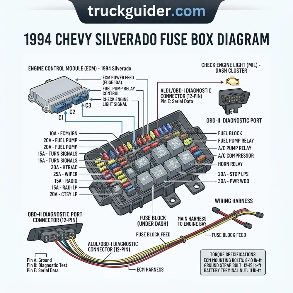
The electrical architecture of the 1994 GMT400 chassis is divided into two primary power distribution hubs. Mastery of these locations is the first step in any diagnostic workflow. The primary fuse block is situated inside the cabin, specifically on the driver-side end of the instrument panel. To access this, you must remove the trim panel cover, which is typically secured by spring clips. This panel houses the majority of the low-amperage circuits controlling interior accessories, the instrument cluster, and interior lighting.
The second, more robust electrical center is the under-hood junction block. This component is located on the driver-side firewall or inner fender well, depending on the engine configuration. This center manages high-amperage feeds, including the fuel pump relay, ignition switch power, and the cooling fan circuits. Unlike the interior block, this unit features a weather-sealed enclosure to protect against coolant flow leaks or external contaminants that could bridge circuits.
When referencing your 1994 Chevy Silverado fuse box diagram, note the presence of the bus bar assembly. The bus bar provides a common positive feed for multiple circuits, allowing for efficient power distribution. In the GMT400 platform, oxidation of these bus bar connections is a common contributor to voltage drop, which can trigger intermittent diagnostic codes in the ECU. When inspecting the fuse box, always verify that the terminal retention force is within OEM specs. Loose terminals are a leading cause of intermittent electrical failures, often masquerading as a faulty component elsewhere in the vehicle. If you find high-resistance connections, utilize an electrical contact cleaner and ensure that ground strap continuity is verified at all primary chassis points.
1994 Chevy Silverado Fuse Box Diagram Reference Tables

The following reference table outlines the typical circuit assignments for the 1994 model year. Always verify these values against the specific label molded into the underside of your fuse box cover, as minor variations existed between light-duty and heavy-duty chassis configurations.
| Circuit Function | Fuse/Relay ID | Amp Rating |
|---|---|---|
| Engine Control Module (ECU) | ECM BATT | 10A |
| Fuel Pump Relay | FUEL PUMP | 20A |
| Instrument Cluster / Gauges | GAUGES | 15A |
| Ignition Switch Feed | IGN 1 | 30A |
| OBD-I Diagnostic Port | ECM IGN | 10A |
| Headlight Circuit | HDLP | 20A |
When replacing fuses, ensure the use of standard ATO/ATC blade-type fuses. Never use ceramic or “hacked” fuses. For high-current relays, ensure the terminal torque spec for the main supply studs is 12 lb-ft to prevent heat buildup and melting of the fuse block plastic.
Common Electrical Failures and Symptoms in GMT400 Trucks
Recommended Best Deal Products


The 1994 electrical system is susceptible to specific failure modes due to its age and environmental exposure. One of the most common issues involves fusible links located near the starter solenoid. If your truck experiences a complete loss of power despite a fully charged battery, inspect these links before suspecting the fuse box. A blown fusible link is a deliberate design feature intended to protect the main harness from catastrophic overcurrent events.
Another frequent symptom involves flickering gauges or erratic oil pressure readings. This is often not a sensor failure but rather a grounding issue. The GMT400 ground distribution block, located behind the engine block or near the firewall, often corrodes. When this ground is compromised, current seeks an alternative path, which can back-feed through the fuse box and cause intermittent ECU resets or a persistent check engine light.
Short to ground conditions are particularly difficult to diagnose. When a circuit continuously pops a fuse, do not simply replace it with a higher-amperage unit. This is a severe fire risk. Instead, utilize a multimeter to check for continuity between the load-side of the fuse terminal and the chassis ground. If continuity exists with the load disconnected, the wiring harness insulation has likely chafed against a metal component, such as the steering column or transmission tunnel. Always inspect the harness routing near the engine block for signs of heat damage from the exhaust manifold or timing chain cover area.
Diagnostic Steps for the 1994 Chevy Silverado Fuse Box
Troubleshooting the electrical system requires a methodical, step-by-step approach. Follow these procedures to isolate issues identified in your 1994 Chevy Silverado fuse box diagram.
1. Verify Battery Voltage: Before touching the fuse box, confirm the battery is providing a stable 12.6V. A low battery voltage can cause relays to chatter, leading to false diagnostic codes.
2. Perform a Voltage Drop Test: Use a digital multimeter to measure the voltage across the fuse terminals. With the ignition in the “ON” position, there should be zero voltage drop across a good fuse. Any reading above 0.1V indicates high resistance or oxidation within the terminal clip.
3. Check the Ignition Switch: If multiple unrelated circuits are failing simultaneously, the ignition switch is the likely culprit. The 1994 model features a multi-pole switch that distributes power to various fuse block sections. A faulty ignition switch often produces symptoms like loss of fuel pump prime or dead accessory circuits.
4. Inspect the ECU Power Circuit: If the truck is throwing a diagnostic code related to the Engine Control Module (ECM), inspect the “ECM BATT” fuse. This circuit provides the keep-alive memory for the ECU. If this fuse is blown, the vehicle will lose stored diagnostic codes every time the ignition is turned off.
5. Terminal Integrity Inspection: Remove the fuse block from its mounting point. Inspect the rear of the unit for signs of thermal damage or discolored plastic. The terminals must have a tight fit around the fuse blades. If a terminal has spread due to heat, it will require a terminal repair kit or a complete fuse box replacement.
6. OBD-I Diagnostic Check: The 1994 model year represents the transition between OBD-I and the later OBD-II standards. Ensure your diagnostic tool is compatible with the ALDL (Assembly Line Diagnostic Link) connector found under the dash. If you cannot establish a connection, check the “ECM IGN” fuse in your 1994 Chevy Silverado fuse box diagram. This fuse powers the diagnostic port.
Never attempt to “jumper” a circuit at the fuse box using uninsulated wire or metal objects. This can cause an immediate short circuit, potentially damaging the engine wiring harness or starting an electrical fire. Always use a proper fused diagnostic jumper lead.
For engine performance issues, ensure your diagnostic steps correlate with mechanical health. A noisy timing chain or low oil pressure will not be solved by replacing a fuse. Always ensure your diagnostic process separates electrical faults from mechanical engine wear.
1994 Chevy Silverado Fuse Box Diagram Questions Answered
Recommended Best Deal Products


How do I know if my fuse box is bad?
The most reliable sign of a failing fuse box is visible heat damage, such as melting plastic around the fuse blades, or a persistent smell of ozone. Additionally, if you measure a high voltage drop across the fuse terminals under load, the internal bus bar or the terminal springs have likely failed due to age or corrosion.
Why does my fuel pump relay click but the pump won’t run?
A clicking relay indicates that the control side (the ECU trigger) is functional. However, if the fuel pump does not run, the load side of the circuit—which draws power directly from the fuse box through the relay contacts—is likely failing. Check the fuel pump fuse and ensure the power feed to the relay socket is delivering a full 12V.
Can I upgrade to an OBD-II port on my 1994 model?
The 1994 Silverado uses an OBD-I ALDL connector. While some enthusiast modifications exist to adapt this to OBD-II, it is not a “plug-and-play” operation. It requires a complete swap of the ECU and the entire engine wiring harness. For most diagnostics, a high-quality OBD-I scan tool is sufficient to retrieve diagnostic codes.
Where is the main ground point for the fuse box?
The fuse box relies on several chassis grounds. The most critical are the body-to-frame grounds located near the base of the firewall and the engine-to-chassis ground strap. If these grounds have high resistance, the entire electrical system can behave erratically, causing the fuse box to ground through sensitive electronic components, which can damage the ECU.
Do all 1994 models use the same diagram?
While the general layout is consistent across the GMT400 platform, trim levels—such as the W/T (Work Truck) versus the Silverado—may have different accessory fuse configurations. Always refer to the decal on the inside of your specific fuse box cover as the ultimate source of truth for your vehicle’s unique equipment level.
Step-by-Step Guide to Understanding the 1994 Chevy Silverado Fuse Box Diagram
Identify – Remove the driver-side dashboard trim panel to expose the plastic fuse box cover.
Locate – Compare the physical fuse orientation with the diagram printed on the internal cover or manual.
Reference – Use the diagram to map the suspected failed circuit to its specific fuse slot number.
Connect – Probe the exposed metal tips of the fuse with a multimeter to verify 12V voltage presence.
Verify – Replace any blown fuse with a unit of the identical amperage; confirm system functionality by turning the ignition to the ‘On’ position.
Troubleshoot – If the circuit fails again, inspect the related harness for short circuits or consult an ECU diagnostic code reader to rule out sensor-related power drops.