2000 Chevy Silverado AC System Diagram: Component Breakdown 2026

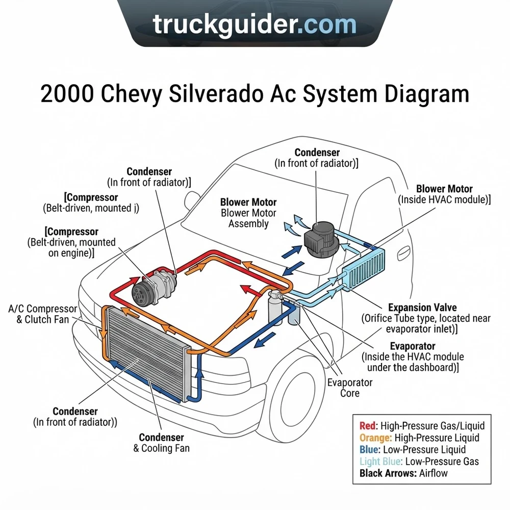
The 2000 Chevy Silverado AC system is a cycling clutch orifice tube design. High-pressure liquid exits the condenser to the evaporator inlet via the orifice tube (located in the liquid line). The compressor relies on the low-pressure cycling switch (dark green/white wire) located on the accumulator to engage the clutch.
📌 Key Takeaways
- R134a capacity is typically 1.8 lbs (29 oz) for standard cab models.
- The orifice tube is found inside the liquid line at the condenser/evaporator connection point.
- System pressures should ideally cycle between 30-40 PSI (low side) and 200-250 PSI (high side) at 85°F.
- Always replace the accumulator/receiver-drier whenever the system is opened to prevent desiccant contamination.
- Professional recovery of refrigerant is required by law before disconnecting any lines to avoid hazardous venting.
The heating, ventilation, and air conditioning system in the GMT800 platform remains a cornerstone of the 2000 Chevy Silverado’s utility. Understanding the 2000 Chevy Silverado AC system diagram is essential for any technician tasked with maintaining or restoring cabin climate control performance. This complex assembly integrates high-pressure refrigerant loops with sophisticated electronic air-handling components. By mastering the flow of R134a and the electrical signaling between the blower motor and the control head, technicians can bypass time-consuming diagnostic guesswork. Whether you are dealing with a faulty heat exchanger or a failing compressor clutch, accurate reference to the system layout ensures that every repair meets factory performance standards and long-term reliability expectations.
2000 Chevy Silverado AC System Diagram: Core Components Explained
Recommended Best Deal Products


To effectively utilize the 2000 Chevy Silverado AC system diagram, one must first identify the primary mechanical and thermal components. The system operates on a closed-loop refrigeration cycle that utilizes the compressor as the heart, pumping refrigerant through a series of heat exchangers to facilitate heat transfer. In the GMT800 architecture, this process is strictly governed by pressure-sensing switches and an orifice tube that meters flow. The following table identifies these critical components and their respective functions within the engine bay and the passenger cabin.
| Component | Primary Function | Placement Location |
|---|---|---|
| Compressor | Pressurizes refrigerant gas | Front engine accessory drive |
| Condenser | Releases heat to atmosphere | Forward of the radiator |
| Orifice Tube | Meters refrigerant expansion | Liquid line near evaporator |
| Evaporator Core | Absorbs interior cabin heat | Inside air handler unit |
| Accumulator | Filters/stores refrigerant | Low-side suction line |
The compressor is belt-driven and engages via an electromagnetic clutch assembly. When the HVAC control module receives a demand signal, it energizes the clutch coil, compressing the low-pressure gas into a high-pressure, high-temperature vapor. This vapor travels to the condenser, where the heat exchanger dissipates thermal energy into the ambient air stream, causing the refrigerant to undergo a phase change into a liquid. Upon exiting the condenser, the high-pressure liquid passes through the orifice tube. This calibrated restriction creates a pressure drop, allowing the refrigerant to enter the evaporator core as a low-pressure mist. As the blower motor forces cabin air across the chilled evaporator fins, heat is absorbed, cooling the interior space. The resulting low-pressure vapor then travels back to the accumulator, which serves as a safeguard against liquid slugging before the cycle repeats. Proper identification of these lines is critical when diagnosing flow restrictions or pressure imbalances in the system.
On 2000 models, ensure the orifice tube is inspected for debris during compressor replacement. Failure to flush the system can result in immediate contamination of the new compressor internals.
How to Read the 2000 Chevy Silverado AC System Diagram Step by Step

Navigating the 2000 Chevy Silverado AC system diagram requires a systematic approach, mapping electrical signals against mechanical refrigerant flow. The GMT800 platform utilizes a specific set of wire color-coded connectors for the A/C pressure switch and clutch relay. Begin your inspection by confirming power at the clutch relay terminal. Using the diagram, locate the PCM (Powertrain Control Module) pinout; the PCM acts as a gatekeeper, analyzing data from the high-pressure switch before granting the ground signal to the A/C compressor relay.
First, verify the R134a refrigerant charge levels. The diagram highlights the high-side and low-side service ports. If static pressure is below 50 PSI, the system may be undercharged, triggering the low-pressure switch to remain open and preventing compressor engagement. Second, examine the blower motor circuit. The blower motor draws significant current, and the diagram identifies the blower resistor block, which controls fan speed. If the motor operates only on high speed, the resistor is likely compromised. Third, trace the vacuum and electrical paths to the air handler actuators. The blend door actuator in the 2000 Silverado is a known failure point; verify that the 12V reference signal is present at the actuator connector using a digital multimeter.
When reading the wiring portion of the diagram, pay close attention to the ground points located near the radiator support. Corroded ground straps often cause intermittent compressor cycling or erratic blower motor behavior. Always cross-reference the wire color charts provided in the diagram with the actual harness to prevent misdiagnosis. If the diagram indicates a specific voltage range for the A/C transducer, ensure your measurement captures the peak-to-peak variance during cycling. This methodical verification—checking electrical signals first, then mechanical pressures—forms the basis of professional diagnostic routines on this platform.
Typical low-side operating pressure for R134a in this system is 25-45 PSI at 80°F ambient temperature. High-side should range from 200-250 PSI depending on airflow through the condenser.
Common 2000 Chevy Silverado AC System Diagram Problems and Fixes
Recommended Best Deal Products


The GMT800 air conditioning system is prone to specific mechanical and electrical fatigue issues. Identifying these faults via the 2000 Chevy Silverado AC system diagram allows for targeted component replacement rather than complete system overhaul. Common failure modes include blend door actuator binding, orifice tube clogging, and accumulator moisture saturation.
- Blend Door Actuator Seizure: This component governs the mix of air from the heat exchanger and evaporator. When the actuator fails, the system often defaults to full heat or full cold. Use the diagram to identify the specific pins for the actuator motor. If the motor hums but fails to move the door, the internal plastic gears have likely stripped.
- Orifice Tube Blockage: If the compressor suffers an internal mechanical failure, metal debris often migrates to the orifice tube. This causes a total restriction in refrigerant flow. A hallmark symptom is a significant temperature differential across the orifice tube housing.
- Accumulator Fatigue: The accumulator contains a desiccant bag designed to absorb moisture. Over time, this bag can rupture, releasing material into the system. If the system has been opened for extended periods, the accumulator must be replaced to prevent freezing of the expansion device.
- Evaporator Core Leaks: Located deep within the air handler, a leaking evaporator is notoriously difficult to diagnose. Use the diagram to isolate the lines leading to the firewall. A refrigerant dye test, viewed through an ultraviolet light at the return duct or drain tube, will pinpoint micro-fractures in the core.
- Blower Motor Resistor Failure: The resistor pack is mounted in the air stream to keep it cool. Frequent failures suggest high resistance in the blower motor itself, causing it to draw excessive amperage. Always test the motor current draw before replacing the resistor to avoid a recurring failure.
Always evacuate refrigerant using certified recovery equipment. Venting R134a into the atmosphere is illegal and dangerous due to potential cold burns and inhalation hazards.
2000 Chevy Silverado AC System Diagram Questions Answered
Where is the orifice tube located on this truck?
According to the 2000 Chevy Silverado AC system diagram, the orifice tube is located inside the liquid line connecting the condenser outlet to the evaporator inlet. It is typically found near the firewall/evaporator service connection.
Why does my blower motor only work on the highest setting?
This is a classic indication of a faulty blower motor resistor assembly. The resistor utilizes a thermal fuse that protects the circuit. When the fuse blows, lower speeds are lost, leaving only the direct-power high-speed setting functional.
How does the pressure switch interact with the PCM?
The high-side pressure switch provides a signal to the Powertrain Control Module to monitor system pressures. If the pressure exceeds 400 PSI or drops below 30 PSI, the PCM removes the ground signal from the compressor relay to prevent mechanical damage.
Can I upgrade my AC system to a different refrigerant?
The 2000 Chevy Silverado AC system diagram is calibrated specifically for R134a. Any attempt to introduce alternative refrigerants or “drop-in” replacements without flushing the oil and replacing seals may lead to catastrophic compressor failure and irreparable damage to the heat exchanger.
Is the blend door actuator difficult to replace?
Replacing the blend door actuator requires access to the air handler, which is situated behind the dashboard. While the process is time-consuming, the 2000 Chevy Silverado AC system diagram clearly shows the wiring harness routing, which is the primary challenge during removal and reinstallation.
Step-by-Step Guide to Understanding the 2000 Chevy Silverado Ac System Diagram
Recommended Best Deal Products


Identify – Locate the compressor assembly at the front of the engine and trace the hoses to the condenser.
Locate – Find the low-pressure cycling switch on the passenger-side accumulator and the blower motor under the passenger dash.
Reference – Use the diagram to verify wire color codes for the compressor clutch relay and the dash HVAC control head.
Connect/Route – Route new lines ensuring rubber O-rings are lubricated with refrigerant oil to prevent high-pressure leaks at fittings.
Verify – Use a multimeter to confirm 12V power at the compressor clutch connector while the AC is set to ‘Max’.
Troubleshoot – If the blower motor fails to spin, check the relay and ground connection identified in the electrical portion of the diagram.