2018 Ford F150 Exhaust System Diagram: Component Breakdown 2026

The 2018 Ford F150 exhaust system configuration features a complex layout starting from the manifold, moving through the catalytic converters, resonator, muffler, and tailpipe. It utilizes high-temperature steel hangers, oxygen sensors (Upstream/Downstream), and flanged gaskets. Proper routing ensures correct backpressure and emission compliance for the 2.7L, 3.5L, and 5.0L engine variants.
📌 Key Takeaways
- Standard OEM exhaust hardware requires M10x1.5 studs and heat-resistant gaskets.
- Oxygen sensor locations are critical: Bank 1/2 Sensor 1 (pre-cat) and Sensor 2 (post-cat).
- Exhaust flange bolts should be torqued to 35-40 ft-lbs to prevent leaks.
- Corrosion at the resonator-to-muffler weld is the most frequent failure point.
- Seek professional exhaust welding services if the structural integrity of the catalytic converter housing is compromised.
The 2018 Ford F-150 utilizes a sophisticated exhaust architecture designed to balance stringent emissions standards with the diverse power output requirements of its engine lineup, ranging from the 2.7L EcoBoost to the high-output 3.5L and the naturally aspirated 5.0L Coyote. Understanding the 2018 Ford F150 exhaust system diagram is essential for professional technicians and advanced DIYers performing maintenance, troubleshooting, or performance upgrades. This system comprises complex plumbing, including integrated catalytic converters, precision-calibrated oxygen sensor locations, and engine-specific manifold geometries. This guide provides a comprehensive overview of the structural layout, inspection protocols, and critical technical specifications required to service the exhaust assembly according to OEM standards.
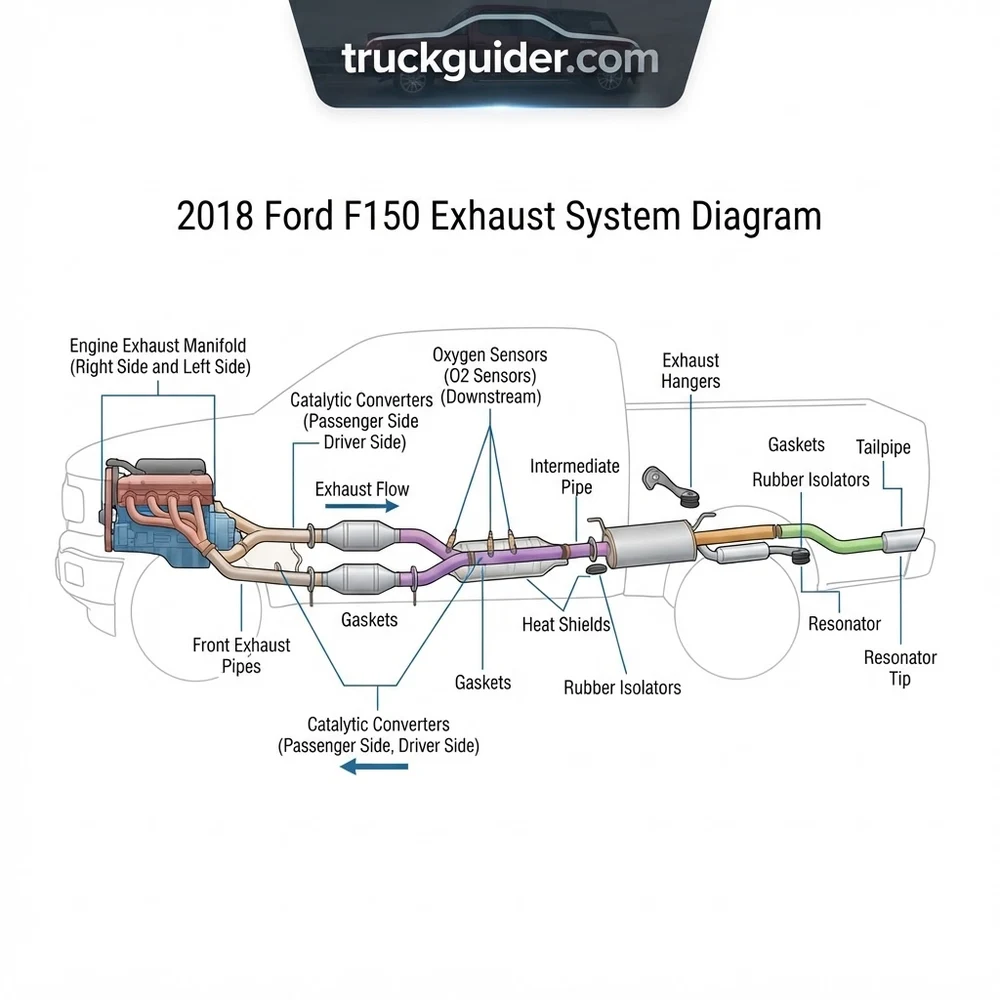
Understanding the 2018 Ford F150 Exhaust System Diagram Layout
Recommended Best Deal Products


The 2018 Ford F150 exhaust system diagram reveals a modular structure that varies significantly based on wheelbase, cab configuration, and powertrain. At the primary stage, exhaust gas exits the cylinder heads through cast-iron or stainless steel manifolds. On EcoBoost variants, these manifolds are integrated into the turbocharger housing assembly. As the gases flow downstream, they encounter the primary catalytic converters, which are monitored by upstream and downstream heated oxygen sensors (HO2S). These sensors are crucial for the Powertrain Control Module (PCM) to adjust fuel trim levels.
The mid-section of the system houses the resonator (on select models) and the intermediate piping, which leads to the main muffler assembly. The final stage consists of the tailpipe, which exits either behind the rear passenger tire or behind the rear bumper, depending on the trim package. It is critical to note that the configuration changes based on the frame length of the vehicle. A Crew Cab with a 6.5-foot bed requires a different intermediate pipe section compared to a SuperCab with a 5.5-foot bed.
| Component | Function | Technical Spec |
|---|---|---|
| Exhaust Manifold | Collects cylinder gases | Torque: 18-20 lb-ft |
| Catalytic Converter | Reduces emissions | Temp Range: 800-1200°F |
| HO2S Sensor | Monitors O2 content | Voltage: 0.1V – 0.9V |
| Exhaust Hanger | Vibration isolation | Hardness: 70 Durometer |
For the 3.5L EcoBoost engines, the turbocharger downpipes are a critical failure point due to high heat cycling. Always inspect the flex-pipe sections for fraying or carbon soot buildup, which indicates an exhaust leak upstream of the catalytic converters.
Variations in Engine Configuration

The exhaust layout is highly dependent on the power plant. The 5.0L Coyote V8 utilizes a traditional dual-bank manifold system that merges into a Y-pipe, whereas the EcoBoost engines route exhaust through the turbos, creating a much higher thermal load on the downstream components. This results in the use of thicker-walled piping and specific heat-shielding configurations that must be accounted for during any replacement procedure.
How to Inspect and Repair the 2018 Ford F150 Exhaust System
Inspecting the 2018 Ford F150 exhaust system requires a systematic approach, starting from the engine block and working toward the exit. Begin by checking the exhaust manifold bolts for signs of snapping or loosening. A ticking sound during cold starts is a common indicator of a manifold gasket failure. Using a mirror and a flashlight, look for carbon streaks around the manifold-to-head mating surface.
Next, examine the catalytic converters. If the PCM throws a P0420 or P0430 diagnostic trouble code, verify the integrity of the downstream O2 sensors before condemning the converter. The O2 sensors should be tested for heater circuit resistance, typically ranging between 3 to 15 ohms depending on the sensor brand and temperature.
Never attempt to service the exhaust system while the vehicle is hot. Catalytic converters can reach internal temperatures exceeding 1200°F and can easily ignite flammable materials or cause severe burns.
Managing Hangers and Isolators
When inspecting the physical structure, verify that all rubber isolators are present and free of dry rot. A sagging exhaust system puts unnecessary stress on the flange bolts, often leading to premature breakage. If the exhaust system is vibrating against the frame, check the center support hanger first.
Utilizing OBD-II Data for Inspection
Integration with the vehicle’s OBD-II port is mandatory for professional diagnosis. Monitor the short-term and long-term fuel trim values using a high-quality scan tool. If the engine is running consistently rich or lean, the exhaust system components—specifically the O2 sensors—are likely providing inaccurate data to the PCM, or there is an unmetered air leak entering the exhaust stream, causing a false lean condition.
Oxygen Sensor Installation Torque: 30 lb-ft. Ensure the use of an anti-seize compound compatible with oxygen sensors to prevent thread galling on the stainless steel exhaust bungs.
Troubleshooting 2018 Ford F150 Exhaust System Diagram Issues
Recommended Best Deal Products


Performance issues often manifest as a loss of power, abnormal exhaust note, or a failure to pass emissions testing. When troubleshooting the 2018 Ford F150 exhaust system diagram, start by identifying the exact location of the symptom. A rasping or rattling noise coming from the middle of the vehicle often points to a failed muffler baffle or a loose heat shield. If the heat shield is the culprit, the repair involves installing stainless steel worm gear clamps to secure the shield back against the pipe, as the original factory spot welds often corrode over time.
Backpressure issues are more complex. If the engine struggles to rev above a certain RPM, a clogged catalytic converter is a primary suspect. Use an infrared thermometer to compare the inlet and outlet temperatures of the converter while the engine is at operating temperature. A properly functioning converter should show a higher outlet temperature than the inlet due to the exothermic reaction occurring within the ceramic honeycomb matrix. If the outlet is significantly cooler, the converter is likely failing or fully obstructed.
Downpipe and Turbocharger Connectivity
For EcoBoost models, the downpipe connection to the turbocharger is a common source of boost leaks. If you observe a “whooshing” sound under acceleration followed by a loss of power, inspect the gasket between the turbo outlet and the downpipe. Replacing this metal-to-metal gasket is a labor-intensive process that requires removing the wheel well liner and, in some cases, the engine mount to gain sufficient clearance.
Upgrading and Maintaining the 2018 Ford F150 Exhaust Configuration
Maintaining the 2018 Ford F150 exhaust system involves regular inspection of all fasteners. The exhaust system is subject to significant environmental exposure, leading to corrosion. Applying a high-temperature rust-inhibiting coating to the flange bolts and weld points can significantly extend the life of the components.
When considering upgrades, such as a cat-back exhaust system, it is vital to select a kit designed specifically for your wheelbase. A kit designed for a SuperCrew 5.5′ bed will not fit a SuperCab 6.5′ bed without extensive modification to the intermediate pipe. Furthermore, ensure that any aftermarket system retains the necessary provisions for the factory O2 sensor locations; failure to do so will result in an immediate Check Engine Light and potential limp-mode operation of the vehicle.
| Upgrade Path | Performance Impact | Maintenance Need |
|---|---|---|
| Stainless Cat-Back | Improved flow, better tone | Check flange bolts yearly |
| High-Flow Downpipes | Increased turbo efficiency | Monitor EGT levels |
| O2 Sensor Spacers | Prevents CEL on mods | Verify emission legality |
Long-Term Reliability and Corrosion Prevention
For vehicles operating in regions where road salt is prevalent, the exhaust system is highly susceptible to “pinhole” leaks caused by internal condensation and external salt spray. Once a pinhole forms in the muffler or piping, the structural integrity is compromised. Inspect the exhaust system during every oil change; look for dark soot patterns on the exterior of the pipes, as these are tell-tale signs of microscopic fractures. Replacing failing components early prevents the spread of corrosion to the more expensive emission-control hardware upstream.
2018 Ford F150 Exhaust System Diagram Questions Answered
Recommended Best Deal Products


Do the 2.7L and 3.5L EcoBoost engines use the same exhaust components?
No, the 2.7L and 3.5L EcoBoost engines feature different turbocharger flange designs and downpipe diameters. While the routing path under the frame is similar, the components are not interchangeable between these two engine variants. Always cross-reference your specific engine code when sourcing replacement manifolds or downpipe sections.
Why does my 5.0L Coyote engine exhaust have a rattling sound?
A rattle in the 5.0L exhaust system is most frequently caused by the internal heat shield on the Y-pipe or the resonator becoming detached. Over time, the spot welds break due to thermal expansion and contraction. This is generally a cosmetic issue, but it should be addressed to prevent the rattling from causing further damage to the hanger isolators.
Can I delete my catalytic converters for better performance?
Modifying or removing the catalytic converters is a violation of federal EPA regulations for on-road vehicles. Furthermore, the 2018 F150 PCM is highly sensitive to O2 sensor readings. Removing the converters will trigger a Check Engine Light and cause the engine to enter a safety mode, significantly reducing performance and fuel economy.
How often should O2 sensors be replaced on an F150?
OEM standards suggest that O2 sensors can last up to 100,000 miles, but they are subject to “lazy” operation as they age. If you notice a decline in fuel economy or a sluggish throttle response, testing the sensors with a lab scope or high-end scan tool is recommended. Replacing them every 80,000 to 100,000 miles is considered good preventative maintenance for emissions efficiency.
Will an aftermarket exhaust void my powertrain warranty?
According to the Magnuson-Moss Warranty Act, an aftermarket exhaust system cannot automatically void your warranty unless the manufacturer can prove the modification directly caused the failure of the warranted part. However, if you install a tune in conjunction with an exhaust upgrade, the powertrain warranty on your engine and transmission may be at risk.
Step-by-Step Guide to Understanding the 2018 Ford F150 Exhaust System Diagram
Identify – Verify your specific engine code to match the correct exhaust system layout.
Locate – Crawl beneath the vehicle to find the suspect leak or failed component relative to the diagram.
Reference – Use the diagram to confirm the sequence of gaskets, heat shields, and support hangers.
Connect/Route – Align the new components ensuring the exhaust configuration matches the factory clearance specs.
Verify – Torque all flange bolts to 35-40 ft-lbs and check for exhaust leaks while the engine is idling.
Troubleshoot – If check engine lights persist, re-examine oxygen sensor connections and wire routing against the diagram.