5.7 Hemi Firing Order Diagram: Complete Setup Guide
The 5.7 Hemi firing order is 1-8-4-3-6-5-7-2. This specific sequence ensures the engine structure remains balanced during operation. Cylinders are numbered 1-3-5-7 on the driver side and 2-4-6-8 on the passenger side. Following this layout is essential for proper ignition timing and system synchronization.
📌 Key Takeaways
- The sequence follows a 1-8-4-3-6-5-7-2 pattern for optimal balance.
- Identify cylinder #1 at the front of the driver-side bank.
- Ensure coil packs are seated correctly to prevent misfires.
- Use the diagram to verify wire routing after spark plug replacement.
- Refer to this guide during ignition system overhauls or engine builds.
Understanding the 5.7 Hemi firing order diagram is an essential skill for any vehicle owner or mechanic looking to maintain the peak performance of this iconic V8 engine. Whether you are dealing with a persistent engine misfire, replacing spark plugs, or performing a complete ignition system overhaul, having a clear visual and technical reference is paramount. In this comprehensive guide, you will learn the exact sequence of combustion, how to identify each cylinder’s position within the engine bay, and the nuances of the Hemi ignition system. By following this blueprint, you can ensure your engine runs smoothly, maintains fuel efficiency, and avoids the mechanical stresses caused by incorrect wiring configurations.
Anatomy of the 5.7 Hemi Ignition System
To fully grasp the firing order, one must first understand the internal structure and configuration of the 5.7-liter Hemi engine. This engine is a longitudinal V8, meaning it is mounted lengthwise in the engine compartment with two banks of four cylinders forming a “V” shape. Each component within the ignition system plays a critical role in delivering high-voltage sparks at the precise moment required for the power stroke.
The term “Hemi” refers to the hemispherical shape of the combustion chambers, which allows for larger valves and improved airflow. However, this unique design also necessitates a specific spark plug layout. In the 5.7 Hemi, the system uses two spark plugs per cylinder, totaling sixteen plugs. This twin-plug configuration ensures a more complete burn of the air-fuel mixture, reducing emissions and increasing power. The ignition timing and the sequence in which these cylinders fire are controlled by the Engine Control Module (ECM), which relies on data from the crankshaft and camshaft position sensors.
In earlier versions of the 5.7 Hemi, the ignition system utilized a “wasted spark” layout where one coil pack sat atop a cylinder but also sent a high-voltage lead to a corresponding cylinder on the opposite bank. In later iterations, the system evolved into a more modern coil-on-plug (COP) design where each cylinder has its own dedicated coil pack, although the dual-plug architecture remained. Understanding which system your vehicle uses is the first step in correctly interpreting any schematic or wiring blueprint.
The 5.7 Hemi Firing Order Diagram and Layout

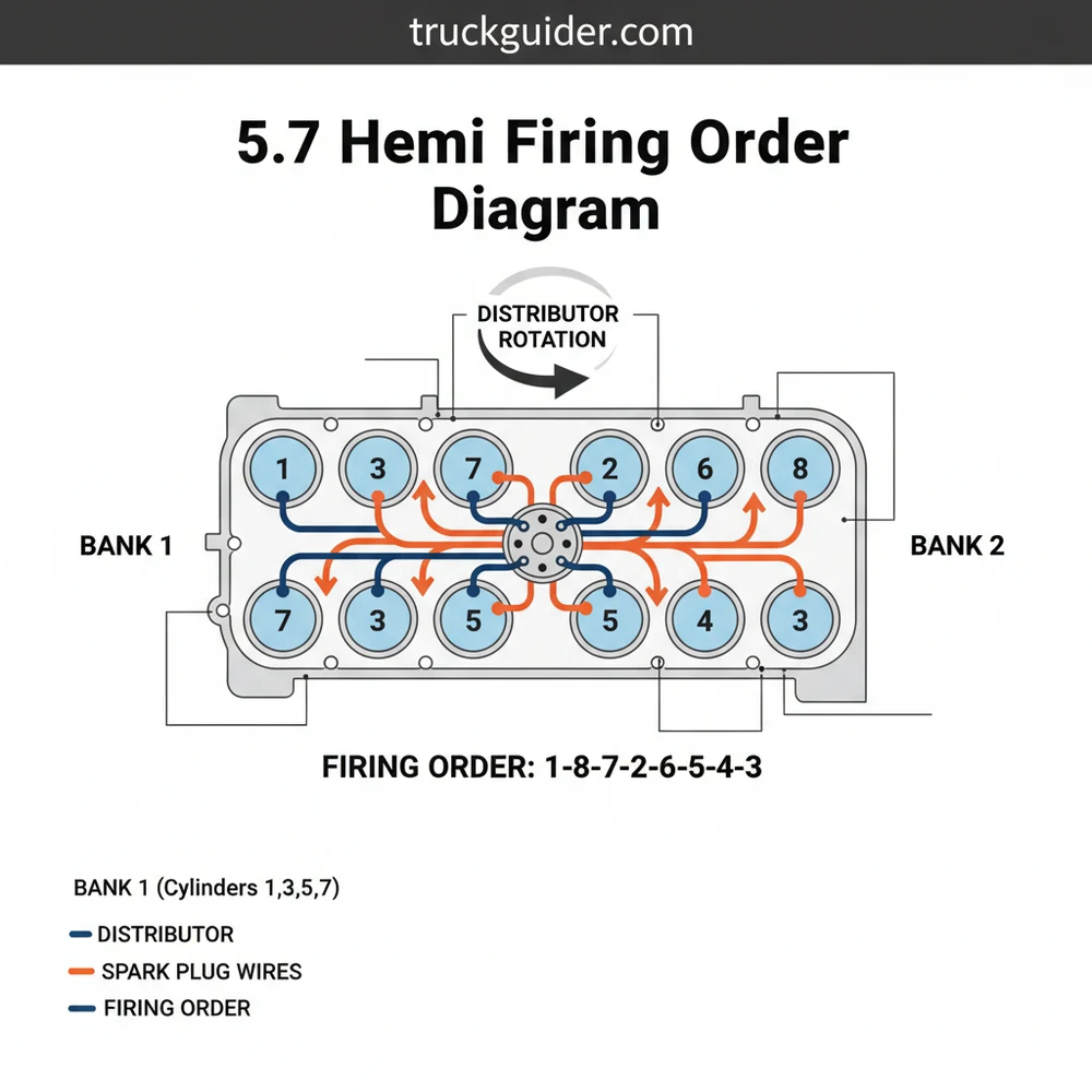
The 5.7 Hemi firing order diagram is a visual representation of how the engine sequences its power strokes to maintain balance and minimize vibration. For the modern 5.7 Hemi engine, the firing order is consistently:
1 – 8 – 4 – 3 – 6 – 5 – 7 – 2
To read the diagram correctly, you must understand the physical layout of the cylinders. When standing in front of the vehicle looking at the engine (the front of the engine being where the belts and radiator are located), the cylinders are numbered as follows:
- ✓ Left Bank (Driver’s Side in US): Cylinders 1, 3, 5, 7
- ✓ Right Bank (Passenger’s Side in US): Cylinders 2, 4, 6, 8
Cylinder 1 is always the forward-most cylinder on the left side (driver’s side). Cylinder 2 is the forward-most cylinder on the right side. The numbering then alternates or follows down the bank toward the firewall.
The 5.7 Hemi firing order starts at the front-left cylinder and concludes with the front-right cylinder. This specific layout is designed to distribute the mechanical load across the crankshaft, preventing excessive torsional stress and ensuring the smooth operation that V8 enthusiasts expect.
[DIAGRAM_PLACEHOLDER: A top-down schematic of a V8 engine block. The left bank is labeled 1-3-5-7 from front to back. The right bank is labeled 2-4-6-8 from front to back. Arrows indicate the firing sequence: 1 → 8 → 4 → 3 → 6 → 5 → 7 → 2. Labels indicate ‘Front of Engine’ and ‘Firewall’.]
The visual breakdown of the schematic often uses color-coding to distinguish between the primary and secondary spark plugs or to highlight the specific wiring harness paths. In the dual-plug system, both plugs in a single cylinder fire nearly simultaneously, though the ECM may offset them slightly under certain load conditions to optimize the flame front within the hemispherical chamber.
Step-by-Step Guide to Using the Firing Order

Interpreting and applying the 5.7 Hemi firing order diagram requires a methodical approach. Whether you are troubleshooting a code or performing a tune-up, follow these steps to ensure accuracy and safety.
1. Identify the Cylinder Orientation
Before touching any wires or coils, orient yourself with the engine. Locate cylinder number one at the front of the driver’s side bank. Marking the coil packs with a permanent marker or masking tape according to their cylinder number can prevent confusion later. This step is the foundation of your entire diagnostic structure.
2. Access the Ignition Components
Depending on your vehicle (Ram truck, Charger, or Jeep), you may need to remove the plastic engine cover and potentially the air intake ducting. Ensure the engine is cool to the touch before proceeding. Use a 10mm socket to remove the bolts securing the coil packs.
3. Map the Wiring Harness
If your Hemi is an older model (pre-2006), you will notice spark plug wires crossing over the intake manifold. Use the firing order schematic to trace each wire. The coil on cylinder 1 will have a wire going to its secondary plug, but may also connect to another cylinder in the “wasted spark” configuration. For newer coil-on-plug models, simply ensure the wiring harness connectors are seated firmly on the correct coil for that specific cylinder number.
4. Inspection and Removal
Remove the coil packs one by one. Inspect the rubber boots for cracks, carbon tracking, or moisture. Using a spark plug socket with a swivel extension, remove the two plugs from each cylinder. Note the condition of the plugs; they can provide a blueprint of the internal combustion health of that specific cylinder.
5. Installation Following the Sequence
When installing new components, work in the order of the firing sequence or bank by bank. Ensure the spark plugs are gapped correctly (usually 0.045 inches for the 5.7 Hemi, but check your vehicle’s specific manual). Hand-thread the plugs to avoid cross-threading the aluminum heads, then torque them to approximately 13-15 ft-lbs.
6. Reconnecting the System
Place the coil packs back onto the cylinders. If you are working on an older system with cross-over wires, double-check the 5.7 Hemi firing order diagram to ensure no wires are swapped. A swapped wire between cylinders 5 and 7, for example, is a common mistake that leads to immediate backfiring and poor idle.
7. Final Verification
Before starting the engine, perform a final visual check. Ensure all electrical connectors are clicked into place and no tools are left near the cooling fan or belts. Start the engine and listen for a steady, rhythmic idle.
Never attempt to pull spark plug wires or coil packs while the engine is running. The ignition system of a 5.7 Hemi generates thousands of volts, which can cause a dangerous electrical shock and damage the sensitive Engine Control Module.
Common Issues & Troubleshooting
Even with a perfect understanding of the configuration, issues can arise. The 5.7 Hemi is a robust engine, but its ignition system is sensitive to wear and environmental factors.
One of the most frequent problems users encounter is a “random/multiple cylinder misfire” code (P0300). When this occurs, the firing order diagram becomes your primary diagnostic tool. By identifying which cylinders are adjacent in the firing sequence (such as 1 and 8, or 7 and 2), you can determine if a problem is localized to one bank or if it is a systemic issue like a failing crankshaft position sensor that is disrupting the entire timing overview.
- ! Rough Idle: Often caused by cracked coil boots or fouled plugs in the 5.7 Hemi’s dual-plug system.
- ! Hemi Tick: While often exhaust or lifter related, an ignition misfire can sometimes mimic the sound of a mechanical tick.
- ! Poor Fuel Economy: If the firing sequence is slightly off due to a sensor delay, the MDS (Multi-Displacement System) may fail to engage.
If you notice a specific misfire code (e.g., P0301 for Cylinder 1, P0304 for Cylinder 4), refer to the layout to locate that exact cylinder. Swap the coil pack from the misfiring cylinder with one from a known good cylinder. If the misfire follows the coil, you have identified the faulty component. If the misfire stays at the same cylinder, the issue may be the spark plugs, the fuel injector, or mechanical compression.
Tips & Best Practices for Maintenance
Maintaining the 5.7 Hemi requires attention to detail. Because this engine uses sixteen spark plugs, the cost and time of a tune-up are doubled compared to a standard V8. However, following these best practices can save you money and prevent future headaches.
Always use the exact spark plug type recommended by the manufacturer. Older 5.7 Hemi engines (pre-Eagle) often respond best to traditional copper-core plugs, while newer versions are designed for long-life iridium or platinum plugs. Mixing these can lead to erratic firing and computer errors.
Another best practice is the use of dielectric grease. Apply a small amount to the inside of the spark plug boot (not the metal terminal) to prevent the rubber from bonding to the plug and to seal out moisture. This is especially important for Hemi engines in trucks or SUVs that may be exposed to heavy rain or engine bay wash-downs.
When looking at the system overview, don’t overlook the condition of the battery and grounding straps. The Hemi’s electronic ignition system relies on a stable voltage. A weak battery can cause “ghost” misfires that appear to be related to the firing order but are actually caused by the ECM struggling to provide enough current to the coils.
Finally, keep a copy of the 5.7 Hemi firing order diagram in your glove box or saved on your phone. Having this blueprint readily available during a roadside emergency or a weekend project ensures that you never have to guess which wire goes where. Consistent maintenance, using quality OEM or high-grade aftermarket components, and adhering to the correct layout will keep your Hemi engine roaring for hundreds of thousands of miles.
The 5.7 Hemi is a masterpiece of modern engineering, combining old-school muscle with sophisticated electronic controls. By mastering the firing order and understanding the structural layout of the ignition system, you empower yourself to handle repairs with confidence and precision. Whether you are a seasoned DIY enthusiast or a beginner, this guide provides the clarity needed to maintain the rhythmic heartbeat of your V8 engine. Understanding the 5.7 hemi firing order diagram is more than just knowing a series of numbers; it is about respecting the design and ensuring every combustion cycle is as efficient and powerful as intended.
Frequently Asked Questions
Where is the number one cylinder located?
On a 5.7 Hemi engine, the number one cylinder is the first component at the front of the engine block on the driver’s side. Knowing this starting point is vital for correctly identifying the rest of the cylinder layout and ensuring the ignition sequence is mapped correctly during maintenance.
What does the 5.7 Hemi firing order diagram show?
This diagram illustrates the specific sequence in which each cylinder fires within the internal combustion system. It maps out the physical layout of the cylinders and the corresponding ignition timing, helping mechanics wire the engine correctly to maintain proper balance and power output across the crankshaft.
How many ignition coils does the 5.7 Hemi have?
The 5.7 Hemi system features a coil-on-plug configuration with eight individual ignition coils. Each coil sits directly above the spark plugs for its respective cylinder. Some versions use two spark plugs per cylinder, meaning there are sixteen plugs total across the entire engine structure that require proper gapping.
What are the symptoms of a bad firing order?
An incorrect firing order configuration typically causes severe engine shaking, backfiring, and significant loss of power. You may experience persistent misfires, check engine lights, and poor fuel economy. If the sequence is wrong, the engine structure may experience mechanical stress due to unbalanced combustion forces during operation.
Can I replace the spark plugs and wires myself?
Yes, replacing these components is a manageable DIY task for most owners. By using a clear 5.7 Hemi firing order diagram, you can ensure that each wire is connected to the correct cylinder. Always work on a cool engine and double-check your layout before starting the vehicle.
What tools do I need for checking the ignition sequence?
To inspect or change the ignition system, you will need a basic socket set with a 5/8-inch spark plug socket and an extension. A torque wrench is recommended to ensure components are tightened to factory specifications, and a gap tool is necessary for setting spark plug distances correctly.


![P0171 Dodge Ram 1500: Fix & Reset Guide [2026]](https://truckguider.com/wp-content/uploads/2026/03/p0171-dodge-ram-1500-featured.webp)