5.7 Liter 5.7 Hemi Engine Diagram: Identification Guide
A 5.7 liter 5.7 Hemi engine diagram provides a comprehensive visual map of the V8’s layout, including cylinder banks, ignition coils, and sensor positions. It helps enthusiasts and mechanics identify components quickly, facilitating more efficient repairs, part replacements, and general maintenance while ensuring all systems are properly connected and functional.
📌 Key Takeaways
- Visualize the internal and external component layout of the 5.7 Hemi.
- Identify the location of major sensors and mechanical assemblies.
- Always follow specific manufacturer torque spec details for assembly.
- Use the diagram to trace wiring paths back to the main ECU.
- Refer to this layout when performing routine maintenance or repairs.
Understanding the intricacies of a legendary powerhouse like the Chrysler-designed V8 requires more than just a passing glance at the manifold; it necessitates a high-quality 5.7 liter 5.7 hemi engine diagram. Whether you are performing a routine tune-up, diagnosing a stubborn misfire, or undertaking a complete rebuild, a visual map is your most valuable tool. This comprehensive guide will walk you through the various systems of the engine, from the accessory belt layout to the complex wiring of the ECU. You will learn how to identify critical sensors, understand the unique dual-ignition setup, and navigate the cooling system with precision. By the end of this article, you will have the technical confidence to use an engine diagram to solve mechanical puzzles and maintain your vehicle’s performance.
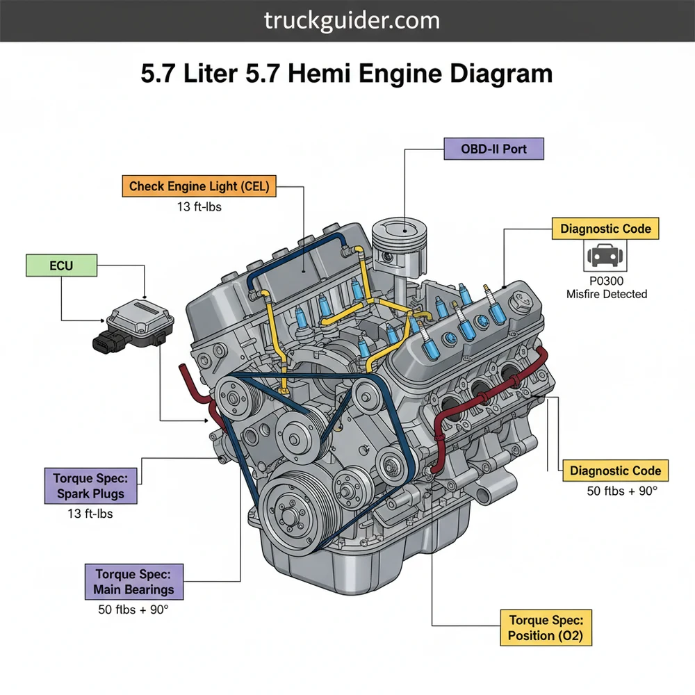
The Anatomy of Power: Main Diagram Description
The 5.7 liter 5.7 hemi engine diagram serves as a blueprint for one of the most successful modern V8 architectures. At its core, the diagram illustrates a 90-degree V-type block, traditionally cast iron, with aluminum alloy cylinder heads that feature the namesake hemispherical (or semi-hemispherical) combustion chambers. When looking at a standard technical drawing of this engine, the components are typically categorized into the block assembly, the valvetrain, the induction system, and the electrical network.
The visual breakdown usually begins at the front of the engine, showcasing the complex serpentine accessory belt routing. This is a critical area for DIYers, as the diagram identifies the positions of the alternator, power steering pump (on older models), water pump, and the air conditioning compressor. Centrally located in the diagram is the intake manifold, which, in many modern iterations, houses the Short Runner Valve (SRV) actuator. You will notice the diagram highlights the “Cross-Flow” head design, where the intake and exhaust valves are situated on opposite sides of the combustion chamber to maximize airflow and volumetric efficiency.
Most 5.7 Hemi diagrams will distinguish between “Pre-Eagle” and “Eagle” versions. The Eagle version, introduced later, features revised cylinder heads, a plastic active intake manifold, and Variable Valve Timing (VVT), which significantly changes the wiring and sensor locations on the diagram.
Color-coding is often employed in these diagrams to differentiate between fluid types. Blue lines typically represent the coolant flow through the water jackets and radiator hoses, while red or brown lines indicate the pressurized oil paths that feed the lifters and the Multi-Displacement System (MDS) solenoids. Understanding these distinctions is vital for correctly identifying which components are responsible for specific engine functions, especially when tracing a leak or a pressure drop.
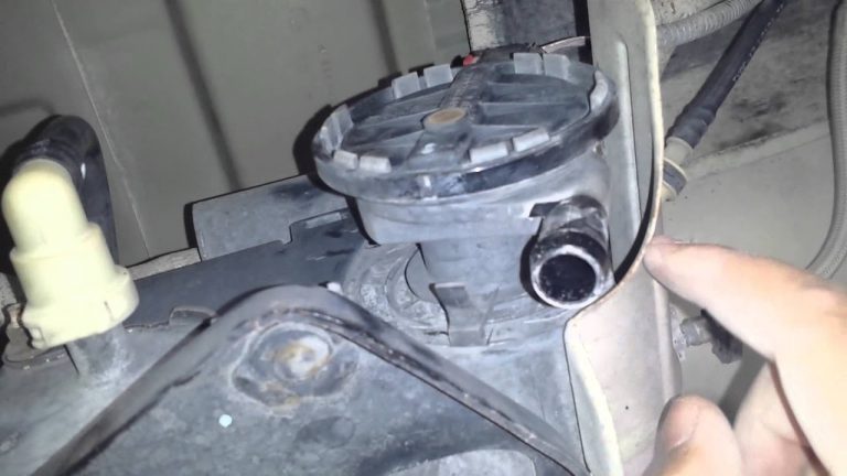
– 5.7 Liter Hemi Engine Component Overview
Deep Dive: Identifying Critical Engine Systems
📤 Share
💾 Download
To effectively use a 5.7 liter 5.7 hemi engine diagram, you must be able to isolate specific systems. The engine is a symphony of mechanical and electronic parts, and the diagram acts as the conductor’s score.
The Valvetrain and Timing Chain
Deep within the center of the “V,” the diagram reveals the single camshaft design. Unlike dual overhead cam engines, the Hemi uses a cam-in-block arrangement. The timing chain is a crucial element shown at the front of the block, connecting the crankshaft sprocket to the camshaft sprocket. If your diagram includes the VVT system, you will see a cam phaser attached to the camshaft gear, which is controlled by oil pressure regulated by the ECU.
The Dual Ignition System
One of the most unique features found on the 5.7 Hemi diagram is the dual-plug setup. Each cylinder has two spark plugs. In earlier models, the diagram shows a “waste-fire” system where a coil pack on one cylinder is connected by a high-voltage wire to a plug on the opposite bank. Later models transitioned to a “coil-on-plug” design where each coil fires both plugs for that specific cylinder. This is a frequent point of confusion that the diagram helps clarify.
The Intake and Fuel Delivery
The fuel rail is depicted sitting atop the intake manifold, housing eight fuel injectors. The diagram will also point out the Electronic Throttle Control (ETC), which has replaced traditional cable-driven throttles. This component is a major interface for the ECU and is often the subject of diagnostic codes related to limp mode or surging idle.
When referencing the timing chain section of the diagram, never attempt to rotate the engine counter-clockwise. This can cause the chain to skip a tooth on the sprocket, potentially leading to catastrophic valve-to-piston contact.
Step-by-Step Guide: How to Interpret and Use the Diagram
📤 Share
💾 Download
Reading a 5.7 liter 5.7 hemi engine diagram is a skill that bridges the gap between a novice enthusiast and a seasoned mechanic. Follow these steps to maximize the utility of your technical illustrations.
Step 1: Orient the Perspective
Engine diagrams are usually drawn from the front-facing perspective (looking at the radiator). Identify the “Front of Engine” arrow. This is essential for determining which side is Bank 1 (Driver’s side in US models, containing cylinder 1) and Bank 2 (Passenger side, containing cylinder 2).
Step 2: Trace the Accessory Belt Path
If you are replacing the accessory belt, locate the tensioner pulley on the diagram. Use the diagram to follow the “ribbed” versus “smooth” side of the belt as it winds around the various pulleys. A misplaced belt can lead to reversed pump rotation or immediate belt failure.
Step 3: Locate the ECU and Main Wiring Harness
The Electronic Control Unit (ECU) is the brain shown at the periphery of the engine diagram. Trace the thickest lines, which represent the main wiring harness, to see how it branches off to the sensors (Oxygen sensors, Crankshaft position sensor, and Knock sensors). This is vital for electrical troubleshooting.
Step 4: Identify the Coolant Flow Route
Follow the lines from the bottom of the radiator to the water pump. Note the location of the thermostat housing. On the 5.7 Hemi, the thermostat is located on the intake side of the water pump, which is a departure from many older engine designs where it sat on top of the manifold.
Step 5: Reference the Torque Spec Table
A comprehensive diagram often comes with a legend containing the torque spec for various bolts. For the 5.7 Hemi, pay close attention to the intake manifold bolts (9 ft-lbs) and the spark plugs (13 ft-lbs). Using the diagram to find the specific bolt and cross-referencing it with the torque table prevents stripped threads in the aluminum heads.
Step 6: Locate the OBD-II Diagnostic Points
While the OBD-II port is inside the cabin, the diagram will show the sensors that feed data to it. When you get a diagnostic code, find the corresponding sensor on the engine diagram (e.g., the Camshaft Position Sensor located behind the water pump) to understand what physical components need inspection.
Step 7: Analyze the MDS System
If your vehicle features cylinder deactivation, locate the four MDS solenoids in the “valley” of the engine block under the intake manifold. The diagram will show the oil passages that these solenoids control to lock or unlock the lifters.
- ✓ 1/2-inch Drive Torque Wrench (for high torque items)
- ✓ 3/8-inch Drive Torque Wrench (for precision items like intake bolts)
- ✓ OBD-II Scanner for reading ECU diagnostic codes
- ✓ Magnetic parts tray to keep track of removed bolts
- ✓ Safety glasses and chemical-resistant gloves
Common Issues & Troubleshooting with the Diagram
The 5.7 Hemi is a robust engine, but it does have known failure points that the 5.7 liter 5.7 hemi engine diagram can help you navigate. One of the most frequent issues is the “Hemi Tick,” which is often caused by broken exhaust manifold bolts or lifter failure. By referencing the diagram, you can identify the exact location of the manifold bolts and the heat shields that must be removed for access.
Another common problem is the illuminating check engine light accompanied by a diagnostic code such as P0300 (Random Misfire). Using the diagram, you can trace the ignition system to check the condition of the wires and coil packs. If you see a P0520 code, the diagram will point you toward the oil pressure sensor, located near the oil filter on the front lower side of the block.
When the ECU detects an issue with the Multi-Displacement System, it may throw a code for an MDS solenoid. The diagram is indispensable here because it shows that the intake manifold must be removed to access these solenoids. Without the diagram, a beginner might waste hours looking for these sensors on the exterior of the block.
If you are experiencing cooling issues, use the diagram to find the “bleeder screw” on the water pump housing. The Hemi system is prone to air pockets, and knowing the highest point in the coolant flow path is essential for properly burping the system.
Maintenance Tips & Best Practices for Longevity
To keep your Hemi running at peak efficiency, adhere to a strict maintenance schedule informed by the component layout. The accessory belt should be inspected every 30,000 miles for cracks or glazing. Use the diagram to identify the wear indicator on the tensioner; if the notch has moved past the limit, it’s time for a replacement.
The timing chain is generally a life-of-the-engine component, but high-mileage engines should be monitored for “slap” or noise. Because the timing chain is hidden behind the front cover and the water pump, use your diagram to understand the labor involved before starting an inspection. Often, it is cost-effective to replace the water pump and the front crankshaft seal at the same time since the diagram shows they share the same access path.
Regarding the oiling system, the 5.7 Hemi with MDS is extremely sensitive to oil viscosity. Always use the manufacturer-recommended 5W-20 oil. The oil passages shown on the diagram for the MDS solenoids are very narrow; using a thicker oil can prevent the solenoids from functioning, triggering a check engine light and a diagnostic code.
Finally, always invest in high-quality OEM or equivalent components. The ECU is calibrated for specific resistance values in sensors like the Crankshaft Position Sensor. Using “no-name” electronic parts often leads to intermittent signals that are difficult to diagnose even with a perfect diagram.
Synthesizing the Information for Success
Owning and maintaining a vehicle with this powerful V8 is a rewarding experience, provided you have the right resources at your fingertips. A detailed 5.7 liter 5.7 hemi engine diagram is more than just a picture; it is a gateway to understanding the synergy between mechanical parts and electronic controls. By learning to identify the accessory belt routing, the timing chain configuration, and the intricacies of the coolant flow, you position yourself as an informed owner capable of handling both routine maintenance and complex troubleshooting.
Remember that the ECU and the OBD-II system are your allies. When the check engine light appears, let the diagnostic code guide you to the specific section of the diagram that requires your attention. Whether you are tightening a bolt to its specific torque spec or replacing a sensor hidden deep in the engine valley, the clarity provided by a comprehensive diagram ensures that the job is done right the first time. Keep this guide and your diagram handy, and your Hemi will continue to deliver its signature roar for many miles to come.
Frequently Asked Questions
Where is the ECU located?
The ECU (or PCM) on a 5.7 Hemi is typically mounted on the passenger side of the firewall or near the coolant reservoir. Consult your specific 5.7 liter 5.7 Hemi engine diagram to find the exact bracket location, as it manages all critical fuel injection and ignition timing functions.
What does the 5.7 Hemi engine diagram show?
This diagram shows the complete layout of the 5.7 Hemi V8 engine. It details the location of the dual spark plugs per cylinder, the Multi-Displacement System (MDS) components, and various sensors. It is used for identifying parts, routing hoses, and understanding the engine’s mechanical and electrical architecture.
What are the head bolt torque specs for a 5.7 Hemi?
For a 5.7 Hemi, the cylinder head torque spec involves a multi-step sequence. Initially, tighten the M12 bolts to 25 ft-lbs, then 40 ft-lbs, and finally a 90-degree turn. Always refer to a service manual or diagram to ensure you follow the correct sequence to prevent head gasket failure.
What are the symptoms of a bad sensor?
Symptoms of a faulty sensor often include a rough idle, poor fuel economy, or a persistent check engine light on the dashboard. You should use a scanner to retrieve a diagnostic code, which indicates whether the issue lies with the manifold pressure, cam position, or oxygen sensors.
Can I replace the spark plugs myself?
Replacing spark plugs on a 5.7 Hemi is a manageable DIY task but requires patience due to the 16-plug setup. Accessing the rear cylinders can be tight, but with the right extensions and a 5.7 Hemi diagram to guide you, you can save significant labor costs at home.
What tools do I need for 5.7 Hemi maintenance?
To work on this engine, you need a standard metric socket set, a torque wrench for accurate tightening, and an OBD-II scanner for electronic troubleshooting. Additionally, a spark plug socket with a swivel joint is highly recommended for reaching the dual plug locations in the hemi heads.


![Dodge Ram 2500 Years to Avoid: Reliability Guide [2026]](https://truckguider.com/wp-content/uploads/2026/03/dodge-ram-2500-years-to-avoid-featured.webp)
![Lifted 3rd Gen Cummins [2026]](https://truckguider.com/wp-content/uploads/2026/03/lifted-3rd-gen-cummins-featured.webp)