Color Code Alpine Stereo Wiring Diagram: Easy Setup Guide
An Alpine stereo wiring diagram identifies wire functions by color: yellow is constant power (hot wire), red is ignition, and black is the ground wire. Speaker pairs use solid colors for positive and striped for negative. Matching these correctly ensures your head unit functions properly without damaging your vehicle’s sensitive electrical system.
📌 Key Takeaways
- Primary guide for matching aftermarket Alpine units to vehicle harnesses
- Correctly identifying the 12V constant and ignition leads is critical
- Always disconnect the vehicle battery to prevent short circuits
- Use high-quality crimp connectors or solder for lasting connections
- Essential for new installations or troubleshooting existing audio issues
Upgrading your vehicle’s audio system with a premium head unit is one of the most rewarding DIY projects a car enthusiast can undertake, but the success of the installation hinges entirely on your ability to interpret the color code alpine stereo wiring diagram. Alpine has long been a leader in car audio, and while they generally adhere to industry standards, the complexity of modern vehicle interfaces means you cannot afford to guess which wire goes where. An incorrect connection could lead to a blown fuse, a fried head unit, or even damage to your vehicle’s sensitive Engine Control Unit (ECU). This comprehensive guide is designed to demystify the harness, providing you with a clear roadmap for identifying power leads, speaker outputs, and specialty trigger wires. By the end of this article, you will understand how to properly map every connection, ensuring your Alpine stereo delivers the high-fidelity sound it was engineered to produce while maintaining the electrical integrity of your car.
Understanding the Alpine Wiring Harness Architecture
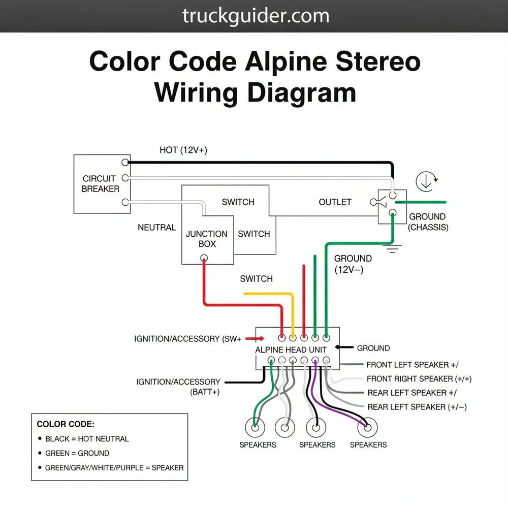
The primary color code alpine stereo wiring diagram follows a structured logic that separates wires into three distinct categories: power and ground, speakers, and auxiliary controls. Alpine utilizes the standard Electronic Industries Association (EIA) color codes, which is a relief for most installers, but the specific implementation and the gauge of the wires are where the details matter.
In the power block, the yellow wire is your constant 12V source, often referred to in electrical terms as the “hot wire.” This wire is responsible for maintaining the stereo’s internal memory, such as radio presets and clock settings, even when the vehicle is turned off. The red wire is the switched ignition lead, which only receives power when the key is in the accessory or “on” position. These two must never be swapped, or your stereo will either drain your battery or lose its settings every time you park. The black wire is the ground wire, which completes the circuit by connecting to the vehicle’s chassis. Unlike a residential neutral wire found in home AC circuits, the DC ground in a car is a direct return to the negative battery terminal.
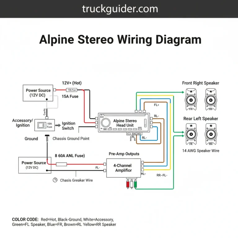
Most Alpine units use 18-gauge or 16-gauge wire for the main power harness. Using a thinner gauge can cause voltage drops, which may lead to the stereo clipping or shutting down during high-volume transients.
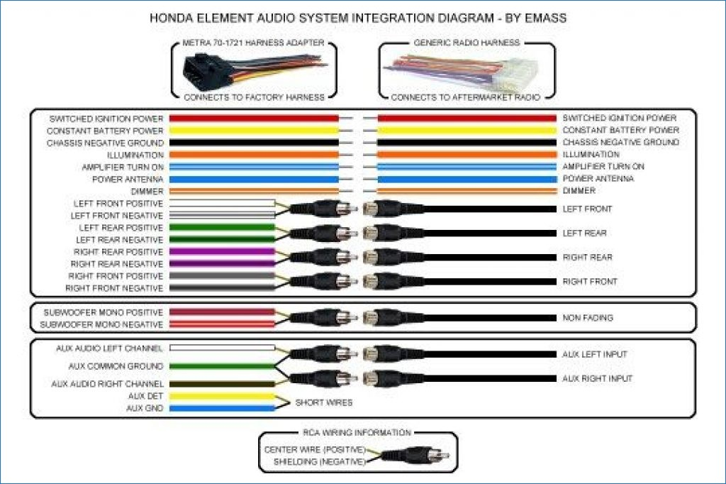
The speaker wiring is organized in pairs with solid colors representing the positive terminal and the same color with a black stripe representing the negative terminal. For example, the front left speaker uses a solid white wire for positive and a white wire with a black stripe for negative. This consistency allows you to maintain proper phase across all four corners of the vehicle. If you reverse the polarity on one speaker, it will move inward while the others move outward, resulting in a phenomenon called “phase cancellation” that effectively kills your bass response.
Step-by-Step Installation and Wiring Guide
Successfully installing your Alpine stereo requires a methodical approach. Before you begin, ensure you have gathered the necessary tools: a wire stripper, crimping tool or soldering iron, heat shrink tubing, and a digital multimeter to verify voltage levels.
- ✓ Step 1: Disconnect the Negative Battery Terminal. This is the most important safety step. It prevents accidental shorts that could blow expensive fuses or damage the Alpine unit’s internal circuitry.
- ✓ Step 2: Prepare the Harnesses. Take the Alpine harness and the vehicle-specific adapter harness to a clean workbench. Strip approximately 1/4 inch of insulation from each wire using a high-quality wire stripper to avoid nicking the copper strands.
- ✓ Step 3: Connect the Power and Ground. Twist the yellow “hot wire” from the Alpine harness to the yellow wire of the adapter. Do the same for the red ignition wire and the black ground wire. If you are grounding directly to the chassis, ensure you use a ring terminal and a clean metal surface, avoiding any painted areas.
- ✓ Step 4: Map the Speaker Wires. Match the four pairs of speaker wires. White (Front Left), Gray (Front Right), Green (Rear Left), and Purple (Rear Right). Ensure the striped “common terminal” or negative wires are matched correctly to their solid counterparts.
- ✓ Step 5: Connect Specialty Wires. The blue/white wire is the remote turn-on lead. This sends a low-voltage signal to turn on external amplifiers. Note that this is different from a traveler wire in three-way home lighting; it is a dedicated DC signal trigger. If your car has a power antenna, you may also see a solid blue wire.
- ✓ Step 6: Secure and Insulate. Use heat shrink tubing or high-quality butt connectors to secure every junction. Never use “twist-on” wire nuts intended for home wiring, as vehicle vibrations will eventually cause them to fall off.
- ✓ Step 7: Verify with a Multimeter. Before plugging the harness into the radio, reconnect the battery and use a multimeter to check the voltage on the yellow and red wires. You should see 12.6V to 14.4V depending on whether the engine is running.
- ✓ Step 8: Final Plug-In and Test. Plug the harness into the back of the Alpine unit, insert the antenna cable, and mount the stereo. Test all functions, including fade and balance, to ensure speakers are wired to the correct locations.
Never connect the orange/white illumination wire to a ground source. Doing so can blow the dashboard light circuit in your vehicle. If your vehicle harness doesn’t have a corresponding dimmer wire, simply cap the orange wire with electrical tape.
Common Issues & Troubleshooting
📤 Share
💾 Download
Even with a detailed color code alpine stereo wiring diagram, issues can arise during the installation process. One of the most frequent complaints is a stereo that won’t turn on. In many cases, this is caused by a poor ground wire connection. In automotive electrical systems, the chassis acts as a giant common terminal. If your ground wire is attached to a plastic bracket or a rusted bolt, the circuit cannot complete.
Another common issue is “alternator whine,” a high-pitched squeal that changes with engine RPM. This is often caused by a ground loop, where the head unit and an external amplifier are grounded at different potential points. Ensuring all audio components are grounded to the same clean metal point can resolve this.
If your Alpine unit powers on but produces no sound, check the blue/white remote wire. If you have a factory-amplified system (like Bose or JBL), the factory amplifier needs that blue/white wire to “wake up.” Without it, the head unit will play music to an amplifier that is essentially asleep. Furthermore, always check the wire gauge of your power connections. If you have extended the yellow hot wire using a gauge that is too thin, the unit may reset itself when you turn up the volume due to insufficient voltage.
If your stereo loses its clock and radio station memory every time you turn the car off, your yellow (constant) and red (switched) wires are likely swapped. Simply reverse these two connections to fix the issue.
Tips & Best Practices for a Professional Finish
Achieving a professional installation goes beyond just following the color code alpine stereo wiring diagram; it involves the quality of the craftsmanship. For the most reliable connection, soldering your wires is the gold standard. When you solder, the physical bond between the copper strands ensures there is zero resistance and no chance of the wires vibrating loose over time. Always slide your heat shrink tubing onto the wire before you join them, and use a heat gun rather than a lighter to shrink the tubing for a clean, uniform look.
If you are not comfortable with soldering, use high-quality nylon-insulated butt connectors. Avoid the cheap plastic ones found in bulk bins; look for connectors that include a heat-shrink sleeve built-in. This provides an airtight seal that prevents the copper from oxidizing, which is especially important in humid climates.
When routing your wires behind the dash, use zip ties to bunch the harness together neatly. This prevents “rat’s nest” wiring that can interfere with the movement of heater vents or mechanical linkages. Also, be mindful of the brass screw or grounding bolt you choose. Ensure it is screwed directly into the steel frame of the car.
Finally, consider the quality of your components. If you are running high-performance speakers, the standard 18-gauge wire in the Alpine harness is sufficient for the short run to the dashboard, but for long runs to the rear deck, upgrading to 16-gauge oxygen-free copper (OFC) wire can improve signal clarity. By taking these extra steps, you ensure that your Alpine stereo installation is not only functional but also durable and capable of providing years of high-quality audio enjoyment.
In conclusion, mastering the color code alpine stereo wiring diagram is the foundation of a successful car audio upgrade. By carefully identifying the hot wire, ensuring a solid connection to the ground wire, and maintaining speaker polarity, you eliminate the most common points of failure. Whether you are identifying a common terminal for your speakers or verifying the voltage of your power leads, a methodical approach is your best tool. With the right tools and this guide as your reference, you can confidently complete your Alpine installation, knowing that every wire is exactly where it needs to be for optimal performance.
Frequently Asked Questions
Where is the Alpine stereo wiring harness located?
The Alpine wiring harness is located directly behind the stereo head unit inside the dashboard. It plugs into the rear of the radio chassis and connects to the vehicle’s factory wiring adapter. To access it, you must remove the dashboard trim panels and unscrew the head unit mounting brackets.
What does the color code alpine stereo wiring diagram show?
This diagram provides a visual map of the 16-pin connector. It shows which colors correspond to specific functions like power, ground, and speaker outputs. It ensures installers can match the stereo’s output to the vehicle’s input, preventing wiring errors that could lead to blown fuses or damaged internal components.
How many wires does an Alpine stereo harness have?
A standard Alpine harness typically features 16 wires. This includes four pairs of speaker wires, a black ground wire, a yellow hot wire, and a red ignition lead. While DC car audio doesn’t use a neutral wire, the negative speaker leads and ground wire complete the electrical circuit loops.
What are the symptoms of a bad Alpine stereo connection?
Common symptoms include the stereo failing to turn on, losing saved radio presets, or intermittent sound cutting out. You might also experience engine noise through the speakers if the ground wire is loose. If the wiring is crossed, you may blow the radio fuse or the vehicle’s main accessory fuse.
Can I install an Alpine stereo myself?
Yes, installing an Alpine stereo is a manageable DIY project if you have a clear wiring diagram. By matching the colors on the Alpine harness to a vehicle-specific adapter, you can perform a professional-grade installation. Just ensure all connections are insulated with heat-shrink tubing to avoid any short circuits.
What tools do I need for Alpine stereo installation?
You will need a set of wire strippers, a crimping tool, and a digital multimeter to test voltage. Plastic trim removal tools are helpful for taking off dashboard panels without scratching them. Additionally, keep electrical tape, zip ties, and a socket set nearby for securing the stereo into the mounting cage.


![Dodge Dakota Towing Capacity Guide: 1987-2011 Ratings [2026]](https://truckguider.com/wp-content/uploads/2026/03/dodge-dakota-tow-capacity-featured.webp)
![How to Tow a Car with a Truck Long Distance: Step-by-Step Guide [2026]](https://truckguider.com/wp-content/uploads/2026/03/how-to-tow-a-car-with-a-truck-long-dista-featured-1.webp)