5.9 Magnum Engine Diagram: Diagnosis & Fix Guide
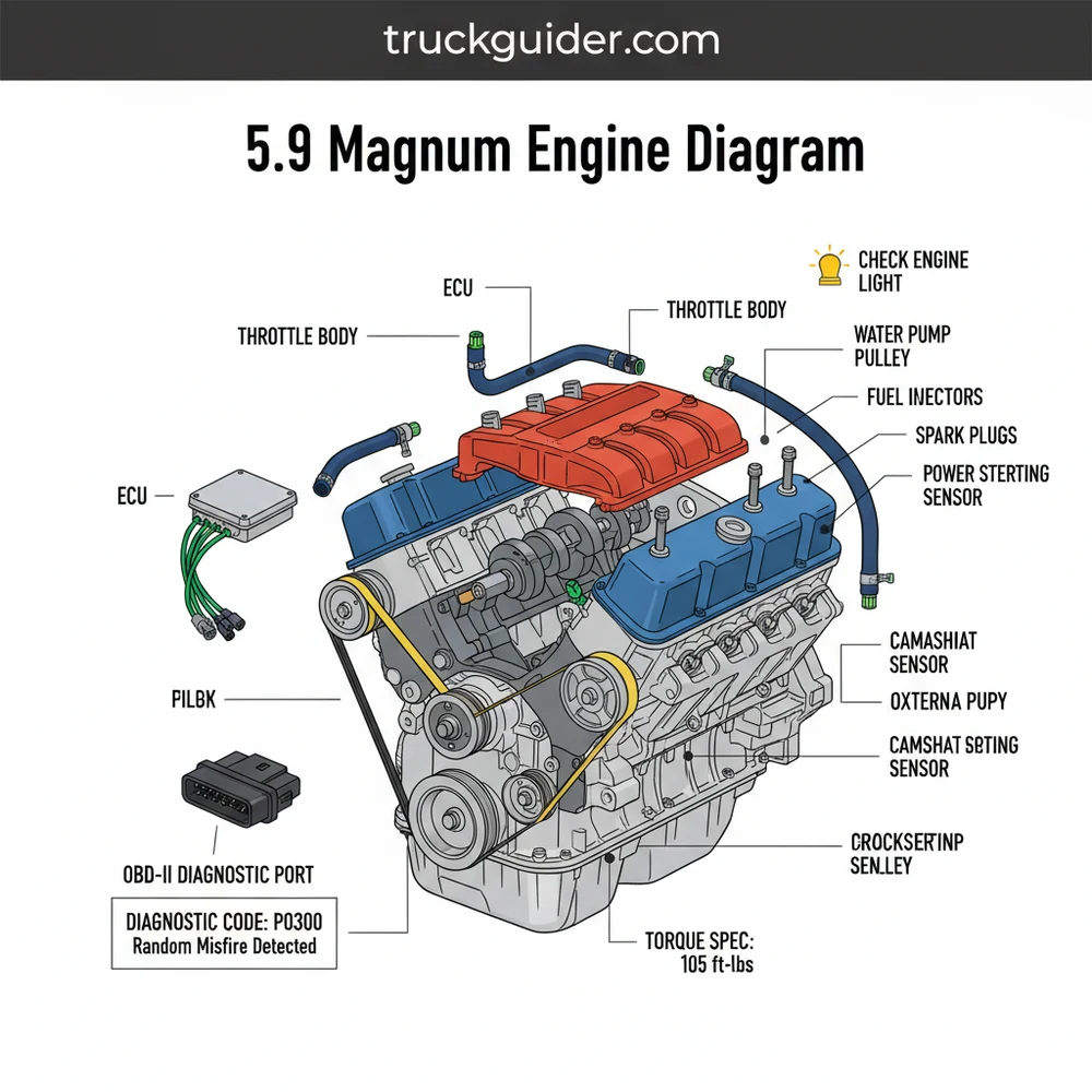
A 5.9 Magnum engine diagram illustrates the layout of essential components like the intake manifold, ignition system, and fuel rails. It identifies the location of sensors connected to the ECU, helping you trace vacuum lines and electrical paths. This visual guide is vital for diagnosing mechanical failures or finding specific bolt patterns during rebuilds.
📌 Key Takeaways
- Provides a visual map of the Dodge/Jeep 360 V8 mechanical and electrical layout
- Crucial for identifying the intake plenum pan and ignition components
- Always disconnect the battery before working near fuel rails or electrical sensors
- Always follow the exact torque spec for the intake manifold to prevent gasket failure
- Use this diagram during teardowns, vacuum leak detection, or sensor replacement
Navigating the complexities of a classic V8 power plant requires precision, and having a detailed 5.9 magnum engine diagram is the first step toward a successful repair or restoration project. Whether you are troubleshooting a persistent misfire, replacing a worn-out water pump, or performing a complete top-end rebuild, understanding the spatial relationship between components is vital. This engine, a staple of the Dodge and Jeep lineups for years, features a unique blend of traditional overhead valve design and modern electronic controls. By utilizing a comprehensive diagram, you gain the ability to visualize the internal and external systems of the 360 cubic inch V8, ensuring that every bolt, sensor, and belt is accounted for. This guide will walk you through the essential schematics, from the intricate accessory belt routing to the critical ECU connections, providing you with the technical confidence needed for professional-grade DIY maintenance.
The 5.9 Magnum is an evolution of the LA block engine. While it shares many physical dimensions with its predecessors, it utilizes a different cylinder head bolt pattern and a unique intake manifold design often referred to as the “Kegler” due to its barrel-like appearance.
The 5.9 magnum engine diagram typically breaks down the engine into several primary subsystems to prevent visual clutter and improve utility. At the front of the engine, the diagram highlights the accessory drive system. This includes the alternator, power steering pump, air conditioning compressor, and the tensioner pulley. Centered among these is the water pump, which is the heart of the coolant flow system. The diagram also illustrates the complex serpentine belt path, which is critical for ensuring that all components rotate in the correct direction and at the proper speed.
Moving to the top of the engine, the diagram identifies the fuel injection and air intake components. You will see the throttle body mounted atop the intake manifold, with various vacuum ports and sensor locations clearly marked. This includes the Idle Air Control (IAC) valve, the Throttle Position Sensor (TPS), and the Manifold Absolute Pressure (MAP) sensor. For engines equipped with OBD-II systems, these diagrams are indispensable for locating the specific wiring harnesses that feed data back to the ECU.
Internally, the diagram provides a look at the valvetrain and timing assembly. The 5.9 Magnum uses a hydraulic roller cam setup, and the diagram will show the orientation of the lifters, pushrods, and rocker arms. Perhaps most importantly for high-mileage engines, the diagram details the timing chain and sprocket alignment marks. These marks are the “north star” for any mechanic performing a timing service, as even a single tooth of misalignment can cause poor performance or engine damage.
To effectively use a 5.9 magnum engine diagram, you must approach the mechanical work with a systematic mindset. Following a structured process ensures that you don’t just see the components, but understand how they interact during the combustion cycle.
- ✓ Step 1: Orient the Diagram to the Vehicle – Begin by standing at the front bumper of the vehicle. Most diagrams are drawn from a “front-looking-back” perspective. Identify the passenger side (Bank 1) and driver side (Bank 2) to ensure you are looking at the correct cylinder bank.
- ✓ Step 2: Identify the Accessory Belt Routing – Before removing any belts, verify the routing against the diagram. The accessory belt must wrap around the crank pulley, water pump, and various accessories in a specific “S” pattern to maintain tension and cooling efficiency.
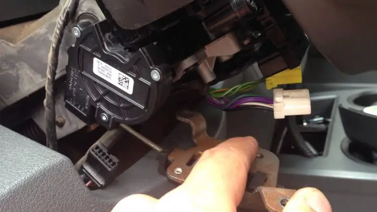
- ✓ Step 3: Locate Electrical Connectors and Sensors – If you are dealing with a check engine light, find the sensors identified by the diagnostic code on your diagram. Trace the wiring from the sensor back to the main harness to check for frays or corrosion.
- ✓ Step 4: Verify Coolant Flow Paths – Use the diagram to trace the coolant flow from the radiator through the lower hose, into the water pump, and through the engine block. This is essential for diagnosing overheating issues or air pockets in the system.
- ✓ Step 5: Apply Specific Torque Specs – A diagram is often accompanied by a torque table. When reinstalling components like the intake manifold or cylinder heads, always use a calibrated torque wrench to meet the manufacturer’s torque spec. For the 5.9 Magnum, the intake manifold bolts require a very specific sequence and low torque to prevent the common plenum gasket failure.
- ✓ Step 6: Check Vacuum Line Integrity – The 5.9 Magnum relies heavily on vacuum pressure for brake boosting and emissions controls. Use the diagram to ensure all small-diameter hoses are connected to their respective ports on the throttle body and charcoal canister.
Always disconnect the negative battery terminal before performing any work identified in an engine diagram involving the electrical system or fuel rails. This prevents accidental shorts to the ECU and reduces the risk of fuel ignition.
When troubleshooting a 5.9 Magnum, the most common issues often involve the ignition and fuel systems. If your vehicle triggers a check engine light, the first step is to use an OBD-II scanner to pull a diagnostic code. For example, a P0300 code indicates a random misfire, which usually points toward the ignition coil, distributor cap, or spark plug wires—all of which are clearly mapped on the engine diagram.
Another frequent problem is the failure of the plenum gasket located on the bottom of the intake manifold. This issue often presents as excessive oil consumption, a pinging sound under acceleration, or a diagnostic code indicating a lean fuel mixture. By referencing the intake manifold section of the diagram, you can see how the steel belly pan is bolted to the aluminum manifold. Because these two metals expand at different rates, the gasket eventually fails, sucking oil into the combustion chamber.
Cooling system failures are also common. If you notice a leak near the front of the engine, the diagram will help you distinguish between a failing water pump weep hole and a leaking bypass hose. Both are located in close proximity but require very different levels of labor to repair.
If you are replacing the timing chain, choose a double-roller upgrade. The factory single-row chain is prone to stretching over time, which can retard ignition timing and cause a loss of low-end torque. A diagram of the timing cover will show you exactly which bolts need to be removed to access this area.
Maintaining a 5.9 Magnum for the long haul requires attention to detail and high-quality components. One of the best practices for this engine is the frequent inspection of the accessory belt. Look for cracking or glazing on the ribs of the belt. If the belt fails, you lose power steering, cooling, and charging simultaneously, which can leave you stranded. Using the 5.9 magnum engine diagram to verify tensioner health is equally important; a weak tensioner can cause the belt to slip, even if the belt itself is new.
For those looking to save money, performing your own sensor replacements is a great place to start. Sensors like the Crankshaft Position Sensor (CKP) are notoriously difficult to reach (located at the back of the block near the bellhousing), but the diagram provides the exact visual location you need to reach it by feel. Replacing this sensor yourself can save hundreds in labor costs at a dealership.
When it comes to the ECU and electronics, keep the grounding points clean. The 5.9 Magnum is sensitive to electrical interference. Your diagram should indicate where the main ground straps connect to the engine block and the chassis. Clean, metal-to-metal contact at these points ensures the OBD-II system receives accurate data from the sensors, preventing “ghost” codes that can be frustrating to diagnose.
Finally, always adhere to the specific torque spec for every bolt you touch. The 5.9 Magnum uses a mix of SAE and some metric fasteners depending on the year, but the internal engine components are strictly SAE. Over-tightening a bolt in the aluminum cylinder heads can lead to stripped threads, turning a simple repair into a costly machining nightmare. By keeping your 5.9 magnum engine diagram handy and following these best practices, you ensure that your V8 remains a reliable workhorse for years to come.
In conclusion, the 5.9 magnum engine diagram is more than just a map; it is an essential piece of equipment for anyone serious about the upkeep of their vehicle. From understanding the complexities of coolant flow to deciphering a diagnostic code via the OBD-II interface, the diagram serves as your primary reference for every mechanical decision. Whether you are performing a simple belt swap or a deep dive into the timing chain assembly, having these visual and technical details at your fingertips is the key to maintaining the power and longevity of this iconic Magnum V8 engine. Proper preparation, the right tools, and a high-quality diagram are the three pillars of automotive success.
Step-by-Step Guide to Understanding the 5.9 Magnum Engine Diagram: Diagnosis & Fix Guide
Identify – Start with identifying the main block and cylinder heads on the diagram to orient yourself to the engine bay.
Locate – Locate the specific sensor or component that triggered the check engine light or is showing signs of physical wear.
Understand – Understand how the OBD-II system communicates with the ECU regarding that specific part’s electrical signals and performance.
Apply – Apply the correct torque spec when reinstalling bolts to ensure a leak-free seal and prevent cracking the aluminum components.
Verify – Verify that all electrical connectors and vacuum lines match the diagram’s routing exactly to avoid misfires or idling issues.
Complete – Complete the repair by clearing any saved diagnostic code with a scanner and performing a thorough test drive.
Frequently Asked Questions
Where is the ECU located on a 5.9 Magnum?
The ECU is typically located on the passenger side firewall or inner fender well, depending on the specific vehicle model. This module acts as the brain of the engine, managing fuel injection timing, spark advance, and monitoring sensor data to ensure the 5.9 Magnum operates within its programmed parameters.
What does a 5.9 Magnum engine diagram show?
This diagram displays the physical placement of the V8 block, cylinder heads, pulleys, and various sensors. It maps out the serpentine belt routing, vacuum hose connections, and the electrical harness layout. It is essential for understanding how the mechanical parts interface with the electronic control systems for proper engine operation.
How many spark plug connections does the 5.9 Magnum have?
As a V8 engine, the 5.9 Magnum features eight spark plug connections. These are connected to a central distributor located at the rear of the engine block. High-voltage pulses are sent through eight separate thick-insulated wires to each cylinder to ignite the air-fuel mixture during the combustion stroke.
What are the symptoms of a bad plenum gasket?
Common symptoms include a rough idle, increased oil consumption, and a persistent check engine light. If the plenum gasket fails, it often triggers a lean diagnostic code, such as P0171, on an OBD-II scanner because the engine is sucking in unmetered air and oil from the lifter valley.
Can I replace the 5.9 Magnum water pump myself?
Yes, water pump replacement is a feasible DIY task with basic hand tools. The process involves draining the coolant, removing the fan shroud and cooling fan, and unbolting the pump from the timing cover. Be sure to clean the mating surfaces thoroughly and apply a new gasket for a seal.
What tools do I need for 5.9 Magnum repairs?
You will need a comprehensive metric and SAE socket set, a reliable torque wrench to meet every specific torque spec, and an OBD-II scanner for reading codes. Additionally, a set of pliers for hose clamps and a fuel line disconnect tool are highly recommended for most top-end engine work.