Dodge Dakota Tail Light Wiring Diagram: Easy Setup Guide
The Dodge Dakota tail light wiring diagram identifies connections for brake, turn, and reverse signals. It typically features a ground wire for the circuit, a hot wire for power, and a common terminal within the housing. Following this schematic ensures correct bulb illumination and prevents short circuits during lighting repairs or replacements.
📌 Key Takeaways
- Visualizes the electrical paths for brake, signal, and reverse lights.
- Identify the ground wire to ensure the circuit completes properly.
- Always disconnect the battery before handling exposed wiring to prevent shorts.
- Use a multimeter to test for power at the connector before replacing bulbs.
- Consult this diagram when upgrading to LEDs or fixing flickering lights.
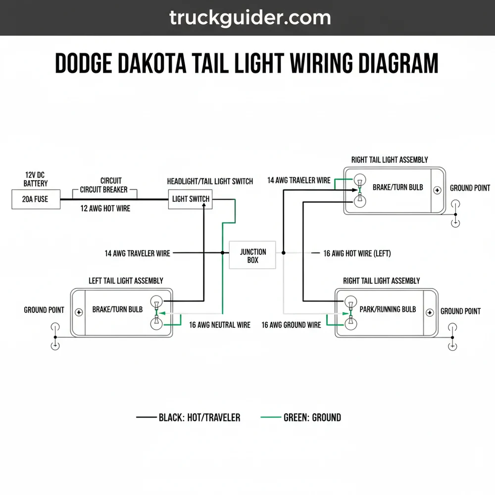
Navigating the complex electrical architecture of a mid-size pickup requires more than just intuition; it demands a precise dodge dakota tail light wiring diagram to ensure every connection is secure and functional. Whether you are currently troubleshooting a flickering brake light, installing an aftermarket off-road lighting kit, or integrating a new trailer harness, having a clear visual and technical map of your vehicle’s rear lighting system is essential. This article provides a deep dive into the specific wiring color codes, terminal locations, and circuit functions that define the Dodge Dakota’s rear electrical grid. By the end of this guide, you will understand how to identify the hot wire, verify the ground wire, and ensure your lighting system operates at the correct voltage to maintain road safety and legal compliance.
Most Dodge Dakota models utilize a negative-ground system where the vehicle’s chassis acts as the primary return path for electrical current. Always verify the integrity of the ground wire before replacing expensive lighting modules or switches.
Decoding the Dodge Dakota Tail Light Wiring Diagram
The primary purpose of a dodge dakota tail light wiring diagram is to illustrate how power flows from the battery, through the various fuses and switches, and finally to the rear lamp assemblies. In a typical Dakota setup, the tail light assembly houses multiple bulbs or LED arrays, each responsible for a specific function: running lights, brake lights, turn signals, and reverse lights. The diagram breaks these down by pin location on the connector and the specific color of the insulation on each wire.
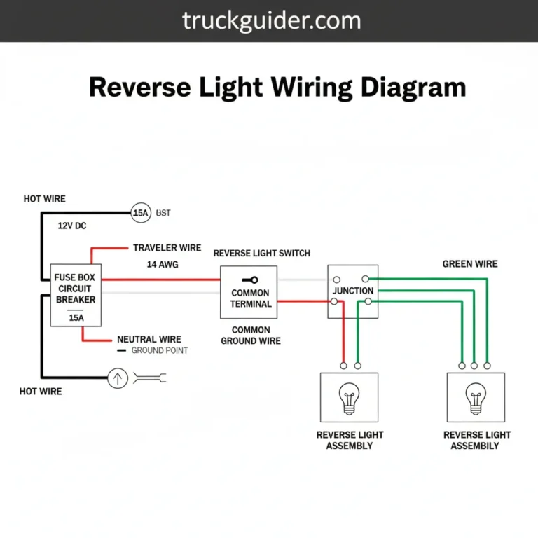
At the heart of the system is the common terminal, which serves as the shared connection point for the ground circuit. In many automotive applications, this is represented by a black or dark green wire that connects directly to the metal frame of the truck. Unlike residential wiring where you might look for a brass screw to secure a neutral wire, automotive systems rely on pressurized plastic connectors and metal pins. The “hot wire” in this scenario is the wire carrying the positive 12-volt charge from the fuse box. For example, on many Dakota generations, the brake light circuit uses a dark green wire with a red stripe, while the running lights often utilize a brown or tan wire.
The diagram also accounts for the “traveler wire” logic found in the multi-function switch located on the steering column. This switch directs the voltage between the turn signal and brake light filaments. Because the Dakota often uses a shared filament for both braking and signaling, the wiring diagram must show how the signal is interrupted when the hazard lights or turn signals are engaged. Understanding these nuances prevents “cross-talk” between circuits, which can lead to situations where applying the brakes causes your front turn signals to glow or vice-versa.
Technical Wire Color and Specification Chart

To effectively use the dodge dakota tail light wiring diagram, you must be able to translate the visual lines into the actual physical wires located behind your truck’s tail light housing. While color codes can vary slightly between the first, second, and third generations of the Dakota, Dodge followed a relatively consistent logic for their truck platforms.
- ✓ Ground Wire (Black): Connects to the common terminal to complete the circuit to the chassis.
- ✓ Running/Parking Lights (Brown or Black/Yellow): Supplies 12V when the headlight switch is in the first or second position.
- ✓ Left Turn/Brake (Dark Green/Red): A dual-purpose wire that carries the pulsed signal for turning and constant signal for braking.
- ✓ Right Turn/Brake (Brown/Pink or Tan): The passenger-side equivalent for signaling and stopping.
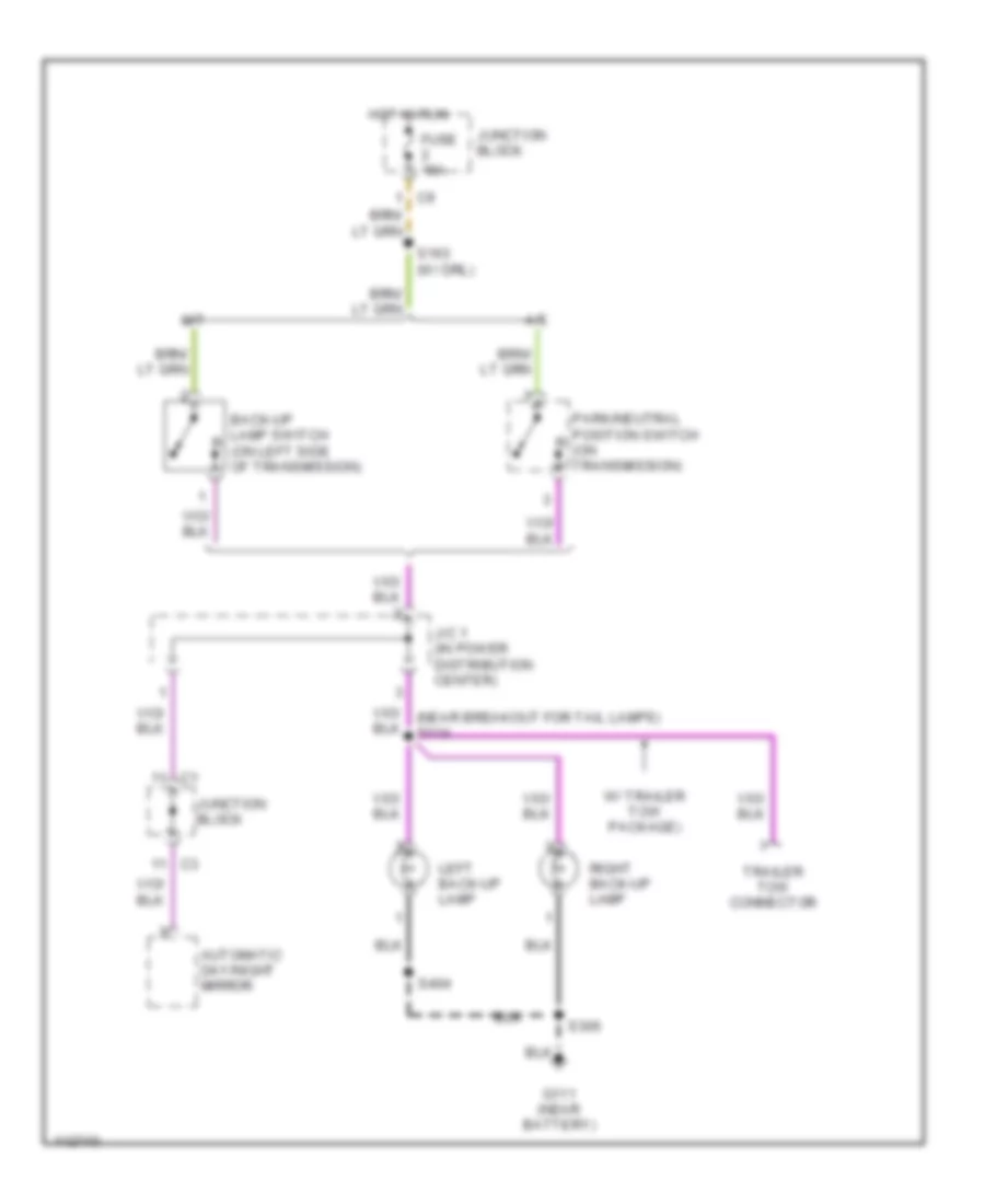
- ✓ Reverse Lights (Violet/White or White/Tan): Only energized when the transmission is in the reverse gear.
The gauge of these wires is typically 18-gauge for signal wires and 16-gauge for the main ground or power leads. Using the correct gauge is critical; if you attempt to use a thinner wire for a high-draw application, the resistance will increase, causing the wire to heat up and potentially melting the insulation or causing a fire.
Never substitute a fuse with a higher-amp rating than specified in your owner’s manual. If a circuit keeps blowing a fuse, it indicates a short to ground or a faulty component, not a need for a larger fuse.
Step-by-Step Guide to Installing or Repairing Tail Light Wiring
If you are using the dodge dakota tail light wiring diagram to perform a repair or installation, following a logical sequence will ensure you don’t miss a critical connection or create a safety hazard.
1. Preparation and Safety: Begin by disconnecting the negative terminal of your truck battery. This prevents accidental shorts while you are probing wires or cutting into the harness. Gather your tools: a digital multimeter, wire strippers, heat-shrink tubing, a soldering iron (or high-quality crimp connectors), and electrical tape.
2. Access the Tail Light Assembly: Lower the tailgate and locate the two or three screws holding the tail light housing in place. Gently pull the housing away from the body. You will see the wiring harness plugged into the bulb sockets.
3. Identify the Circuits: Using your dodge dakota tail light wiring diagram, locate the harness connector. If you are replacing a damaged section, use your multimeter (set to DC voltage) to test each pin while an assistant operates the lights (reconnect the battery briefly for this step, then disconnect again before cutting).
4. Verify the Ground: Locate the ground wire (usually black). Ensure it has a solid connection to the common terminal. If the ground is loose or corroded, the lights may act erratically, such as dimming when the brakes are applied. In the electrical world, the ground acts similarly to a neutral wire in a home circuit, providing the return path for the current.
5. Stripping and Splicing: If you are adding a trailer harness, use a “T-connector” if possible. If you must splice, strip approximately 1/2 inch of insulation from the target wire. Slide a piece of heat-shrink tubing onto the wire before making your connection.
6. Soldering the Connection: For the most reliable connection, solder the wires together. This ensures minimal resistance and prevents the vibration of the truck from loosening the joint over time. If using a crimp, ensure you use the correct size for the wire gauge.
7. Insulation and Protection: Move the heat-shrink tubing over the joint and shrink it with a heat gun. This protects the copper from moisture and corrosion. Finish by wrapping the section in high-quality automotive-grade electrical tape.
8. Final Testing: Reinstall the bulbs into the housing and secure the housing back onto the truck. Reconnect the battery and test every function: left turn, right turn, hazards, running lights, and reverse. Ensure the voltage at the bulb socket is consistently between 12.4V and 14.2V while the engine is running.
Apply a small amount of dielectric grease to the bulb sockets and connector pins. This non-conductive grease seals out moisture and prevents the “green crust” of corrosion that commonly plagues Dodge truck electrical systems.
Common Issues & Troubleshooting with Dakota Wiring
Even with a perfect dodge dakota tail light wiring diagram, issues can arise due to the age of the vehicle and environmental exposure. One of the most frequent problems is the “dim light” syndrome. This occurs when the ground wire has a high resistance connection to the chassis. Because the electricity cannot easily return to the battery, the voltage drops, and the bulb glows faintly.
Another common failure point is the brake light switch located under the dashboard near the brake pedal. If your wiring diagram shows power reaching the switch but not leaving it when the pedal is pressed, the switch itself is likely burnt out. Additionally, check the “PDC” (Power Distribution Center) under the hood. Dakotas are known for having integrated relays in the fuse box that can fail over time.
Watch for signs of melted plastic around the bulb sockets. This usually indicates that a previous owner installed bulbs with too high a wattage, or there is a loose connection causing an arc. An arc generates intense heat which can damage the brass screw-like contacts inside the socket or the plastic housing itself.
Advanced Considerations: LED Upgrades and Voltage Regulators
Many Dakota owners choose to upgrade their traditional incandescent bulbs to modern LEDs. While LEDs are more efficient and brighter, they interact with the dodge dakota tail light wiring diagram differently. Because LEDs have very low resistance, the truck’s flasher relay may think a bulb is blown out, leading to “hyper-flashing” (a very rapid turn signal blink).
To fix this, you may need to install a load resistor on the “hot wire” of the turn signal circuit. This resistor mimics the load of a standard bulb. When installing these, be aware that they get very hot; they should be mounted to the metal body of the truck rather than tucked against plastic wiring or the tail light housing.
Furthermore, always pay attention to the voltage stability. A fluctuating voltage can shorten the life of expensive LED modules. If your multimeter shows voltage swinging wildly when the engine revs, you may have an issue with the alternator’s voltage regulator, which is managed by the truck’s Engine Control Module (ECM) in newer Dakota models.
Maintaining Your Truck’s Electrical Integrity
To ensure the longevity of your repair, treat the wiring as a critical safety system. Periodically inspect the harness where it runs along the frame rail. Road debris and salt can abrade the outer loom, exposing the colored wires to the elements. If you notice any exposed copper, seal it immediately to prevent the wire from wicking moisture up into the main harness.
When choosing replacement components, look for “OEM-style” connectors. While universal kits are cheaper, they often lack the weather-tight seals found on original Dodge equipment. Investing in high-quality components and following the dodge dakota tail light wiring diagram precisely will save you hours of troubleshooting in the future and keep your truck visible and safe for years to come.
In conclusion, the electrical system of your Dodge Dakota doesn’t have to be a mystery. By identifying the common terminal, understanding the role of the ground wire versus the hot wire, and utilizing the correct gauge of wiring for your repairs, you can maintain a professional-grade lighting setup. Whether you are performing a simple bulb swap or a full harness rebuild, the diagram remains your most valuable tool in the garage. Always prioritize clean connections, proper insulation, and rigorous testing to ensure your Dakota remains a reliable workhorse on the road.
Frequently Asked Questions
Where is the tail light connector located?
The connector is located directly behind the tail light assembly housing. Access it by lowering the tailgate and removing the mounting screws. Once the assembly is pulled away from the body, you will see the wiring harness plugged into the common terminal at the rear of the unit.
What does the tail light wiring diagram show?
This diagram illustrates the specific wire colors and routes for the brake lights, turn signals, and reverse lamps. It defines how the hot wire delivers power to each bulb and how the ground wire returns current to the chassis, ensuring each lighting function operates independently and correctly.
How many wires does a Dodge Dakota tail light have?
Most models feature a three or four-wire setup per side. This includes a ground wire, a wire for the parking lights, and another for the combined brake and turn signal. In some configurations, a traveler wire might be referenced during custom trailer hitch wiring or switch installs.
What are the symptoms of a bad tail light ground?
A faulty ground wire often causes dim lights, flickering, or multiple bulbs illuminating simultaneously when they shouldn’t. If the common terminal loses its connection to the chassis, the current may backfeed through other circuits, causing erratic behavior across the entire rear lighting system of your truck.
Can I replace the tail light wiring myself?
Yes, replacing the tail light harness is a straightforward DIY task. By following a wiring diagram, you can identify which hot wire corresponds to which signal. Most harnesses use plug-and-play connectors, making it easy to swap out damaged sections without needing advanced electrical engineering skills.
What tools do I need for tail light wiring?
You will need a Torx or Phillips screwdriver to remove the assembly, a multimeter or test light to verify power, and wire strippers if you are making repairs. While a neutral wire is rarely used in DC systems, you should have electrical tape or heat shrink tubing ready for connections.

![PBJ Paint Code Guide: Hydro Blue Pearl for Jeep, Ram, Dodge [2026]](https://truckguider.com/wp-content/uploads/2026/03/pbj-paint-code-featured.webp)
![PWQ Paint Code: Diagnosis & Repair [2026]](https://truckguider.com/wp-content/uploads/2026/03/pwq-paint-code-featured.webp)