Dodge Ram 1500 Vacuum Line Diagram: Easy Setup Guide
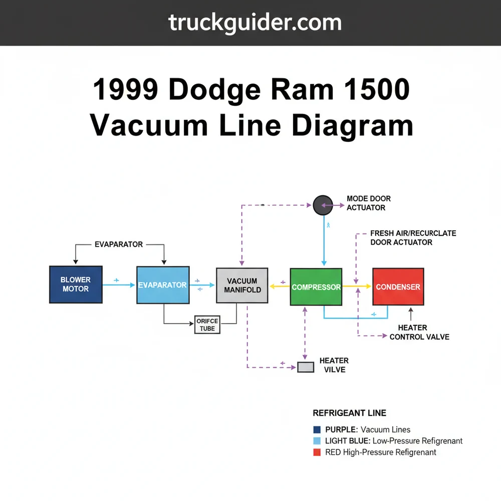
The 1999 Dodge Ram 1500 vacuum line diagram illustrates the connections between the engine intake manifold and the HVAC actuators. It controls air distribution across the evaporator and condenser. If vents are stuck on defrost, check the vacuum check valve near the firewall or the lines feeding the interior selector switch.
📌 Key Takeaways
- Main purpose is to control airflow direction through the HVAC box
- The vacuum check valve is the most critical component for consistent operation
- Always check for brittle or cracked lines near high-heat engine areas
- Use a hand-held vacuum pump to test individual actuator doors
- Use this diagram when air fails to switch between floor, dash, and defrost
Maintaining the climate control system in a classic second-generation truck requires more than just a basic understanding of mechanics; it requires a precise roadmap of the pneumatic network that governs air distribution. If you have ever found yourself frustrated by air that only blows out of the defrost vents regardless of your setting, you are likely dealing with a vacuum leak. Obtaining and understanding a 1999 Dodge Ram 1500 vacuum line diagram is the first critical step in restoring the functionality of your HVAC system. This diagram serves as a blueprint, showing how vacuum pressure travels from the engine’s intake manifold or the diesel vacuum pump through a series of check valves, reservoirs, and switches to ultimately move the doors inside your air handler. Without this visual guide, identifying a cracked line hidden deep behind the dashboard or tucked away in the engine bay becomes an exercise in futility. In this comprehensive guide, we will explore every connection, component, and control mechanism to ensure your cabin remains comfortable regardless of the weather outside.
Detailed Breakdown of the Vacuum Diagram Components
The vacuum system in a 1999 Dodge Ram 1500 is an intricate web that bridges the gap between engine performance and cabin comfort. At its core, the system relies on a constant supply of negative pressure to actuate various doors within the HVAC housing. To read a 1999 Dodge Ram 1500 vacuum line diagram effectively, you must first identify the primary components that appear on the schematic.
The source of the vacuum differs depending on your engine. For gasoline models (the 3.9L V6, 5.2L V8, and 5.9L V8), vacuum is generated directly by the intake manifold. On the 5.9L Cummins diesel models, a dedicated mechanical vacuum pump is used because diesel engines do not produce sufficient manifold vacuum. From the source, a primary supply line runs toward the passenger side firewall. Along this path, you will find the vacuum check valve. This small, often black-and-white plastic cylinder is a one-way street; it allows vacuum to be pulled from the system but prevents air from rushing back in when the engine is under heavy load or turned off.
Once past the check valve, the line splits. One branch leads to the vacuum reservoir, commonly referred to by enthusiasts as the “football” due to its shape. This tank stores a reserve of vacuum pressure, ensuring that when you accelerate—causing manifold vacuum to drop—your HVAC doors don’t suddenly shift positions. The other branch enters the cabin through a rubber grommet in the firewall, leading directly to the back of the HVAC control head on the dashboard. Inside the dashboard, the vacuum is distributed via a multi-colored harness. Each color corresponds to a specific actuator:
- ✓ Red Line: Controls the fresh air/recirculation door.
- ✓ Yellow Line: Manages the floor heat actuator.
- ✓ Brown/Tan Line: Operates the defrost vent door.
- ✓ Blue/Green Lines: Direct air to the panel vents.
While the vacuum system controls “where” the air goes, it works in tandem with the mechanical side of the HVAC system. This includes the blower motor, which pushes air through the evaporator (for cooling) and the heat exchanger or heater core (for warming). The refrigerant cycles through the compressor and condenser to remove heat, but without the vacuum lines directing that treated air through the proper return duct or output vent, the entire process fails to keep the passenger cabin at the desired temperature.
[DIAGRAM_PLACEHOLDER: 1999 Dodge Ram 1500 HVAC Vacuum Schematic showing Source -> Check Valve -> Reservoir -> Firewall -> Control Head -> Actuators]
|
[CHECK VALVE] —-> [VACUUM RESERVOIR]
|
(FIREWALL GROMMET)
|
[HVAC CONTROL SWITCH]
/ | | \
[RECIRC] [DEFROST] [PANEL] [FLOOR]
On the 1999 Dodge Ram, the default position for the HVAC doors is “Defrost.” This is a safety feature. If the system loses vacuum pressure entirely due to a leak or a failed pump, the spring-loaded actuators will automatically direct all air to the windshield to ensure visibility is maintained in cold weather.
Step-by-Step Guide to Interpreting and Repairing Vacuum Lines
📤 Share
💾 Download
Interpreting a vacuum line diagram and applying it to your vehicle requires a methodical approach. Because these trucks are now decades old, the original rubber lines have often become brittle, leading to cracks that are nearly invisible to the naked eye. Follow these steps to diagnose and repair your system using the diagram.
Step 1: Identify the Vacuum Source
Begin your inspection at the engine. For gas engines, locate the small port on the passenger side of the intake manifold. For Cummins diesels, locate the vacuum pump mounted near the power steering pump. Ensure the main supply hose is firmly attached and not “mushy” from oil exposure. Oil contamination can soften rubber, causing the line to collapse under suction.
Step 2: Inspect the Check Valve and Reservoir
Trace the line from the source to the check valve. You can test the check valve by removing it and blowing into both ends; air should only flow in one direction. Next, follow the line down toward the vacuum reservoir. On most 1999 models, this is tucked under the cowl or mounted to the passenger side inner fender. If the reservoir is cracked, the system will lose pressure every time you step on the gas pedal.
Step 3: Access the Firewall Pass-Through
The main vacuum line enters the cabin through a small plastic tube bundled with other wires. Locate this on the firewall and check for signs of rubbing or heat damage. It is common for this line to break right at the firewall, which completely disconnects the cabin controls from the vacuum source.
Step 4: Remove the Dashboard Trim
To see where the lines go inside, you must remove the center bezel of the dashboard. This usually snaps off with a gentle pull. Once the bezel is removed, unscrew the HVAC control head. On the back, you will see a round plastic connector with several colored vacuum lines. This is the “brain” of your air distribution system.
Step 5: Match Colors to the Diagram
Using your 1999 Dodge Ram 1500 vacuum line diagram, verify that each colored line is seated deeply into the rubber multi-plug. If a line has popped out, the specific vent it controls will stop working. For example, if the red line is loose, you will not be able to switch between fresh air and recirculated air.
Step 6: Use a Vacuum Pump for Testing
If you cannot find a visible break, use a hand-held vacuum pump (like a MityVac). Connect it to individual lines at the control head and pump it up. The line should hold a vacuum. If the needle on the gauge drops, follow that specific color-coded line to its actuator under the dash to find the leak.
Step 7: Inspect Actuator Diaphragms
The vacuum actuators are small metal or plastic cans with a rubber diaphragm inside. If the diaphragm tears, the actuator cannot pull the door open. These are located behind the glove box and near the driver’s side floorboard. Use the vacuum pump to see if the actuator rod moves when pressure is applied.
Step 8: Final Reassembly and Testing
Once repairs are made, start the engine and cycle through every setting: Defrost, Mix, Floor, Panel, and Recirc. Listen for the “hiss” of vacuum moving the doors. If the transitions are crisp and the air moves to the correct vents, your repair is complete.
Never use high-pressure compressed air to “clear” vacuum lines. The HVAC actuators and the control head switch are delicate and designed for negative pressure only. Applying positive pressure can rupture the internal diaphragms, necessitating an expensive and difficult dashboard teardown.
Common Issues & Troubleshooting
📤 Share
💾 Download
The most frequent complaint involving the 1999 Dodge Ram 1500 vacuum line diagram is the “Wild Vent” syndrome. This occurs when air comes out of the vents during idling but switches to the defrost vents as soon as you accelerate or climb a hill. This is a classic symptom of a failing check valve or a cracked vacuum reservoir. Because the engine produces less vacuum under load, the reservoir is supposed to take over. If it can’t hold a charge, the system defaults to the defrost position.
Another common issue involves the blower motor. While the blower motor is electrical, the vacuum system determines which “pathway” the air takes through the air handler. If you hear the blower motor running loudly but very little air is coming out of any vent, you may have a “blocked” condition where two vacuum doors are fighting each other or a main door has become disconnected from its actuator rod.
The evaporator and heat exchanger can also be sources of secondary frustration. If your vacuum lines are perfect but the air is not cold, the issue lies within the refrigerant cycle—likely the compressor or a leak in the evaporator. However, if the air is ice cold but only blows on your feet, the 1999 Dodge Ram 1500 vacuum line diagram is your best friend in locating the failed floor actuator or the yellow vacuum line responsible for that movement.
If you find a small crack in a hard plastic vacuum line, you don’t always need to replace the entire run. A short piece of rubber vacuum hose with an inner diameter that matches the outer diameter of the plastic line can act as a perfect “sleeve” to bridge the gap and restore the seal.
Tips & Best Practices for Vacuum System Maintenance
To ensure your HVAC system remains reliable for years to come, proactive maintenance of the vacuum network is essential. Heat is the primary enemy of rubber and plastic components. Over time, the heat from the engine bay causes the factory lines to become “petrified” and brittle. When performing any work under the hood, be extremely careful not to bump or lean on these lines, as they can snap like dry pasta.
One of the best upgrades for a 1999 Dodge Ram owner is to replace the main engine bay vacuum lines with high-quality silicone tubing. Silicone is significantly more resistant to heat and ozone than standard rubber, meaning it won’t crack or rot nearly as quickly. When replacing lines, always do them one at a time to avoid crossing connections, and refer back to your 1999 Dodge Ram 1500 vacuum line diagram frequently.
Additionally, keep an eye on your return duct and cabin air intake areas. Debris like leaves or pine needles can get sucked into the air handler, putting physical strain on the vacuum-operated doors. If a door is physically stuck by debris, the vacuum actuator might burn out its internal seal trying to pull it shut. Regular cleaning of the cowl area beneath the windshield wipers can prevent this.
Finally, consider the quality of your replacement parts. When a check valve fails, avoid the temptation to buy a generic “one-size-fits-all” valve from a bin at the local auto parts store. Using an OEM-spec valve ensures the cracking pressure is correct for the Ram’s specific vacuum requirements. Similarly, ensure that the lines are routed away from the hot exhaust manifold and the moving parts of the belt drive to prevent melting or physical shearing.
In conclusion, while the vacuum system might seem like an antiquated technology in the age of fully electronic climate controls, it is a robust and logical system once you understand its layout. By using a detailed 1999 Dodge Ram 1500 vacuum line diagram, you transform a confusing mess of colored tubes into a manageable DIY project. Whether you are replacing a faulty compressor or simply trying to get your vents to blow air in the right direction, a healthy vacuum system is the foundation of a comfortable ride. Take the time to inspect your lines, test your actuators, and maintain your reservoir; your truck’s HVAC system—and your passengers—will thank you for it.
Frequently Asked Questions
Where is the vacuum check valve located?
The vacuum check valve on a 1999 Dodge Ram 1500 is typically located on the passenger side firewall. It connects the engine intake manifold to the vacuum reservoir. This valve prevents vacuum loss during acceleration, ensuring your HVAC doors remain in the selected position without defaulting to the windshield defrost vent.
What does this vacuum line diagram show?
The 1999 Dodge Ram 1500 vacuum line diagram shows the routing from the engine to the HVAC control head. It details how vacuum pressure moves doors within the heater box to direct air past the evaporator or heater core, and out through the desired vents like floor or dash.
How many vacuum connections does the control switch have?
The HVAC mode selector switch usually features a multi-port vacuum connector with five to seven individual colored lines. Each color-coded line corresponds to a specific actuator door, such as the recirculate door or the defrost door, allowing the vacuum to trigger different air path configurations in the cabin.
What are the symptoms of a bad vacuum line?
Common symptoms include air only blowing from the defrost vents, a hissing sound behind the dashboard, or the compressor failing to cycle correctly. Even if your refrigerant levels are perfect, a vacuum leak will prevent the system from directing cold air to the face vents during operation.
Can I replace these vacuum lines myself?
Yes, replacing vacuum lines is a common DIY task. Most lines are plastic or rubber and can be swapped using basic hand tools. Ensure you use the correct diameter tubing and refer to the 1999 Dodge Ram 1500 vacuum line diagram to maintain proper routing and avoid leaks.
What tools do I need for vacuum line repair?
To repair vacuum lines, you will need a vacuum pressure gauge, a pair of needle-nose pliers, and a sharp utility knife for cutting new tubing. A small amount of silicone lubricant can help slide rubber connectors onto the plastic lines or the ports on the HVAC control head.

![2012 Dodge Ram 1500 Interior [2026]](https://truckguider.com/wp-content/uploads/2026/03/featured-893818eb-768x768.webp)