Diagram Ford F150 IWE Vacuum Lines: Broken Down by Model Year

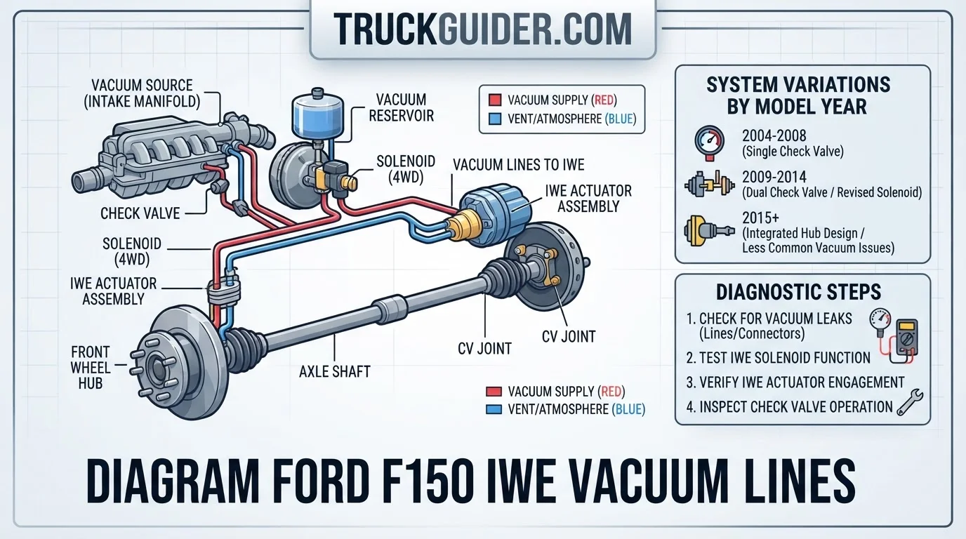
Dealing with a front-end grinding noise in your truck often points directly to a failure in the 4WD engagement system. The diagram ford f150 iwe vacuum lines serves as the vital roadmap for identifying leaks, cracked hoses, or solenoid malfunctions that prevent your hubs from disengaging properly. Understanding these lines is the primary step to resolving 4×4 engagement issues and preventing costly long-term damage to your wheel ends.

Reference Data for Diagram Ford F150 IWE Vacuum Lines
Recommended Best Deal Products


How to Read This Reference Chart
This table outlines the essential components found in a standard diagram ford f150 iwe vacuum lines. The “Function” column describes the mechanical role of each part, while the “Typical Status” column indicates how the component behaves under default engine vacuum conditions.

Note that “Verify for exact year” is required because Ford changed solenoid locations and hose routing between the 2004–2008 and 2009–2014 generations. Always cross-reference the specific vacuum routing diagram provided in your owner’s manual or factory service manual for your specific engine configuration (e.g., 5.4L vs 5.0L).

Detailed Analysis of Diagram Ford F150 IWE Vacuum Lines
The IWE system is a vacuum-based mechanism. When the engine is running and the truck is in 2WD, the vacuum solenoid is energized, allowing engine vacuum to pull the IWE actuators inward, effectively disconnecting the wheel hubs from the axle shafts.
If a vacuum line cracks—which is common due to engine heat and road vibration—the system loses its “hold” on the actuators. The internal springs force the gears to engage even while in 2WD. This causes the characteristic grinding noise as the teeth struggle to align at speed.
System Specifications and Design Advantages
Recommended Best Deal Products


One of the primary advantages of this system is fuel efficiency. By physically disconnecting the front wheels from the axles in 2WD, the truck does not waste energy rotating the front drivetrain components. This design feature helps minimize parasitic power loss.
However, the system has notable disadvantages. The reliance on delicate plastic vacuum lines means that off-road debris or simple age-related brittleness can cause system-wide failures. Understanding the specifications of the vacuum routing ensures you replace components with the correct heat-resistant tubing.
How to Read the Diagram Ford F150 IWE Vacuum Lines Step by Step
Start at the vacuum reservoir (usually located near the battery or firewall). Trace the primary line leading to the IWE solenoid, typically mounted on the passenger side firewall.
Follow the lines running downward toward the front frame rails. Use a handheld vacuum pump to test individual segments for leaks, comparing findings against your specific diagram.

Audible — Listen Free for 30 Days
One free credit a month and thousands of titles included.
Listen Free for 30 DaysEnsure the lines reach the back of the front wheel knuckles. Check the rubber grommets for dry rot, as these are the most common failure points for vacuum integrity.
Identifying Generation-Specific Differences
Recommended Best Deal Products


When searching for a diagram ford f150 iwe vacuum lines, realize that the 2004–2008 and 2009–2014 models have different solenoid placements. The earlier models often experienced more issues with the vacuum check valve allowing fluid to migrate into the lines.
Modern F-150s (2015+) have moved toward more sophisticated electronic transfer case controls, though they still utilize the IWE vacuum actuators. Always ensure the diagram you are referencing matches your model year to avoid incorrect hose connections or pressure ratings.
✨ Key Benefits of Proper Maintenance
Extended Component Life
Preventing the IWE gears from grinding saves the internal wheel end splines from stripping, which can cost thousands in axle and hub repairs.
Reliable 4WD Engagement
A properly functioning vacuum system ensures that your 4×4 actually engages when you switch into high or low range, keeping you safe on trails.
What If It Still Doesn’t Work?
If you have verified the integrity of the vacuum lines using the diagram and confirmed the solenoid is switching, but the grinding persists, you may have a failed IWE actuator itself.
- Inspect the actuator seals for internal leakage.
- Check the wheel hub splines for wear or metal shavings.
- Verify the transfer case shift motor is actually sending the signal for 4WD.
- Consult a professional technician if vacuum pressure is present but the hub fails to engage or disengage, as the internal spring may be broken.
Professional repair for a full IWE replacement usually ranges from $400 to $800 depending on your region and specific truck configuration.
Audible Premium Plus — Annual Membership
12 audiobook credits up front, plus the full Audible catalogue.
See Annual PlansConclusion
Fixing front-end grinding requires a precise approach to the diagram ford f150 iwe vacuum lines. By systematically testing the solenoid, check valves, and individual hose segments, you can isolate the leak and restore proper 4WD function. These systems are designed for durability, but they require periodic inspection for leaks. Based on professional maintenance standards, checking these lines annually can prevent catastrophic hub damage and save significant repair costs. Always ensure you are using a diagram specific to your model year to ensure accurate results.
Key Takeaways
-
✓
Master the IWE vacuum path from the solenoid to the front hub actuators. -
✓
Compare vacuum system differences between pre-2015 models and 2015-2026 iterations. -
✓
Learn diagnostic procedures to isolate leaks using a handheld vacuum pump. -
✓
Understand the pros and cons of vacuum-based engagement versus electronic alternatives. -
✓
Identify key features of the check valve and solenoid that frequently fail.
❓ Frequently Asked Questions
1
What is the Ford F150 IWE system?
The Integrated Wheel End (IWE) system is a vacuum-operated mechanism that connects the front wheel hubs to the drivetrain. It uses engine vacuum to pull the hub gear away from the axle, allowing for 2WD operation. When vacuum is lost, springs force the hubs to engage, locking them to the axle.
2
How does the IWE vacuum system work?
The system physics involves a vacuum solenoid that directs manifold vacuum to the wheel ends. In 2WD, vacuum is applied to hold the IWEs in the disengaged position. When 4WD is selected, the solenoid vents the vacuum to the atmosphere, allowing the internal spring to engage the hub with the axle shaft.
3
Why is the IWE vacuum diagram important?
A diagram is essential because vacuum lines snake through the frame and chassis, making them difficult to track. Knowing the exact routing helps in identifying potential chafing points or disconnection sites where leaks occur, saving hours of guesswork during the diagnostic process.
4
What are the benefits of the IWE system?
The primary advantage of the IWE system is fuel efficiency in 2WD mode by reducing drivetrain drag. Unlike permanent locking hubs, it allows for ‘on-the-fly’ engagement while driving, providing a balance between convenience and mechanical performance when transitioning from pavement to rough terrain.
5
How can I get started with IWE troubleshooting?
Start by inspecting the vacuum supply line at the solenoid near the battery tray. Use a vacuum gauge to verify 15-20 in-Hg of vacuum at idle. If vacuum is low or absent, work backward toward the manifold or forward toward the hubs to isolate the specific line or component failure.
6
Why does my truck make a grinding noise in 2WD?
The grinding is the IWE gears rubbing because insufficient vacuum is failing to hold the hub in the fully disengaged position.
![2019 Ram 1500 Reliability [2026]](https://truckguider.com/wp-content/uploads/2026/03/featured-4dc19a40.webp)
![P226C Code 6.7 Cummins: Diagnose & Fix [2026]](https://truckguider.com/wp-content/uploads/2026/03/p226c-code-6-7-cummins-featured.webp)