Dodge Caliber Fuse Box Diagram: Diagnosis & Fix Guide
The Dodge Caliber fuse box diagram identifies the Totally Integrated Power Module (TIPM) located in the engine compartment, adjacent to the air filter housing. This central hub controls power to the ECU and various sensors. Referencing the map allows you to resolve a diagnostic code or check engine light by replacing blown fuses.
📌 Key Takeaways
- The TIPM acts as both a fuse box and a computer-controlled power module.
- Identifying the ECU fuse is critical for resolving engine management issues.
- Always check the diagram before using an OBD-II scanner for simple power faults.
- Use a fuse puller to avoid damaging the plastic TIPM housing.
- The diagram is located on the underside of the fuse box cover for quick reference.
Finding the 2007 Dodge Caliber fuse box diagram is often the first step in diagnosing an electrical gremlin that has left you stranded or frustrated. Whether your power windows have stopped responding, your radio has gone silent, or your headlights are flickering, the fuse box is the nerve center where you can quickly identify and resolve the issue. In the 2007 Dodge Caliber, the electrical architecture is unique because it relies on a “Totally Integrated Power Module” (TIPM) rather than a traditional split system between an interior and engine-bay fuse box. Having an accurate 2007 dodge caliber fuse box diagram allows you to bypass expensive mechanic fees by identifying which specific circuit has failed. In this comprehensive guide, we will walk you through the location of the module, the specific layout of the fuses and relays, and the diagnostic steps required to keep your vehicle’s electrical system running smoothly.
Unlike many other vehicles from this era, the 2007 Dodge Caliber does not have a fuse panel inside the cabin or under the dashboard. All primary fuses and relays are housed within the TIPM located in the engine compartment, near the air filter housing.
Understanding the 2007 Dodge Caliber TIPM Layout
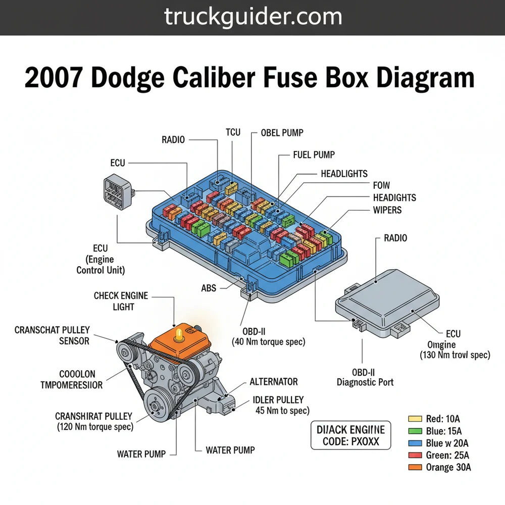
The 2007 Dodge Caliber utilizes a single, centralized fuse box known as the Integrated Power Module. This component is essentially the “brain” for the vehicle’s electrical distribution, acting as an interface between the battery and various modules like the ECU (Electronic Control Unit). The diagram for this vehicle is arranged in a grid-like fashion, with components labeled with an “Alpha-Numeric” code (e.g., M1, M13, M20).
Inside the box, you will find three primary types of protectors: Mini-fuses, J-Case fuses (high-draw), and Relays. The mini-fuses generally handle smaller loads like the OBD-II port or the instrument cluster, while J-Case fuses are reserved for heavy-duty applications like the starter motor or the radiator cooling fans that manage coolant flow. The layout is designed to be accessible, but it requires a careful eye to distinguish between the various amperage ratings, which are color-coded for safety. For instance, a blue fuse typically signifies 15 amps, while a yellow one indicates 20 amps.
[ TOP OF ENGINE COMPARTMENT ]
_
| [M1] [M2] [M3] [M4] [M5] [M6] [M7] |
| [M8] [M9] [M10] [M11] [M12] [M13] [M14]|
| |
| [ J1 ] [ J2 ] [ J3 ] [ J4 ] [ J5 ] [ J6 ]|
| [ J7 ] [ J8 ] [ J9 ] [ J10] [ J11] [ J12]|
| |
| [R1] [R2] [R3] (Relay Section) |
|_|
Simplified representation of the 2007 Dodge Caliber TIPM internal layout.
Primary Fuse and Circuit Identification
To properly use the 2007 dodge caliber fuse box diagram, you must match the fuse number on the underside of the plastic lid with the corresponding circuit. Here are the most critical fuses for daily operation:
- ✓ M1 (15 Amp Blue): Center High Mounted Stop Light (CHMSL)
- ✓ M6 (20 Amp Yellow): Power Outlet, Rain Sensor, and Cigar Lighter
- ✓ M10 (15 Amp Blue): Ignition Off Draw (IOD) – Critical for the clock and radio memory
- ✓ M13 (20 Amp Yellow): Instrument Cluster, Interior Lights, and Siren
- ✓ M20 (15 Amp Blue): Interior Lighting and steering wheel modules
- ✓ J13 (60 Amp Yellow): Main Ignition Feed (The heavy hitter for starting the car)
- ✓ J17 (40 Amp Green): ABS Motor Feed
Step-by-Step Guide to Troubleshooting Your Fuses

When an electrical component fails, don’t rush to the mechanic. Following a systematic approach can save you time and money. Here is how to interpret and act upon your 2007 dodge caliber fuse box diagram findings.
Before touching any fuses, ensure the ignition is completely OFF and the keys are removed. This prevents accidental short circuits or triggering a check engine light by momentarily disconnecting a live sensor circuit.
- Locate the TIPM: Open the hood of your Dodge Caliber. On the driver’s side, near the battery and the air intake duct, you will see a black plastic box. This is your Integrated Power Module.
- Access the Internal Panel: There are plastic tabs on the side of the box. Press these inward and lift the cover straight up. On the underside of this cover, you will find a printed version of the 2007 dodge caliber fuse box diagram which acts as your primary reference.
- Identify the Symptom: Match your car’s issue to the circuit name. For example, if your OBD-II scanner won’t power up, look for the fuse labeled for the diagnostic port or data link connector.
- Visual Inspection: Use a fuse puller (often located inside the lid or purchased separately) to remove the suspected fuse. Look at the metal wire inside the translucent plastic. If the bridge is broken or the plastic is charred, the fuse is blown.
- Test with a Multimeter: For J-Case fuses or relays where a visual check is difficult, set your multimeter to the “Continuity” or “Ohms” setting. Touch the probes to the two small metal test points on top of the fuse. A “beep” or a zero reading indicates the fuse is good.
- Replace and Verify: Replace the blown fuse with one of the exact same amperage. Never use a higher amp fuse, as this can lead to a fire or damage the ECU.
- Clear Codes: If the blown fuse caused a check engine light, you might need to use an OBD-II scanner to clear the diagnostic code after the repair is complete.
Technical Context: Fuses and the Drive System
📤 Share
💾 Download
It is important to understand that the fuse box doesn’t just power the radio; it manages the vital signs of your engine. For instance, the sensors that monitor the timing chain position and the rotation of the accessory belt send signals back to the ECU, which is powered through the TIPM. If the fuse for the PCM (Powertrain Control Module) or ECU is compromised, the engine may crank but refuse to start, often leading owners to incorrectly assume a mechanical failure like a snapped timing chain.
Similarly, if your car is overheating, the problem might not be the coolant flow itself but rather a blown relay for the radiator fans. Without these fans, the radiator cannot dissipate heat when the vehicle is idling. Always check the high-amp J-Case fuses related to “Cooling Fan” before assuming you have a water pump or thermostat issue.
The 2007 Dodge Caliber is known for “TIPM failure.” If you replace a fuse and it blows again immediately, or if multiple unrelated electrical systems fail at once (e.g., windshield wipers turn on when you honk the horn), the internal circuitry of the TIPM may be damaged. In this case, a simple fuse swap will not fix the underlying problem.
Common Issues & Troubleshooting
The 2007 Dodge Caliber is prone to several specific electrical hurdles. By referencing your 2007 dodge caliber fuse box diagram, you can narrow down these frequent headaches:
1. The “No-Start” Condition: If the car won’t start and you hear a clicking sound, check J-Case fuse J13. If the fuse is fine, check the battery terminals. Ensure they are tightened to the correct torque spec (typically around 10-12 lb-ft) to ensure a solid connection to the TIPM.
2. Headlight Failure: The Caliber does not use traditional fuses for the headlights. Instead, the TIPM uses “Smart FETs” (Field Effect Transistors) to monitor current. If a bulb shorts out, the TIPM shuts down that circuit. You may need to disconnect the battery for 10 minutes to reset the module after replacing the bulb.
3. Check Engine Light and OBD-II: If your check engine light is on but your OBD-II scanner cannot communicate with the vehicle, check the fuse for the Diagnostic Link Connector (DLC). Without power to this pin, you cannot retrieve the diagnostic code necessary for repairs.
Tips & Best Practices for Maintenance
Maintaining the electrical health of your Dodge Caliber involves more than just swapping fuses. Follow these industry best practices to ensure long-term reliability:
- Use Dielectric Grease: When replacing fuses in the engine bay, a small dab of dielectric grease on the contacts can prevent corrosion caused by humidity and road salt.
- Keep Spare Fuses: Always keep a variety pack of mini and J-Case fuses in your glovebox. The Caliber uses specific sizes that may not be available at every rural gas station.
- Monitor the Accessory Belt: A worn accessory belt can cause the alternator to vibrate, leading to inconsistent voltage. This “dirty power” can stress the fuses and the ECU over time. Ensure your belt is tensioned correctly and free of cracks.
- Battery Health: A weak battery is the number one enemy of the Dodge TIPM. If voltage drops below a certain threshold during cranking, the TIPM can “glitch,” causing permanent software errors that mimic blown fuses.
Conclusion
Mastering the 2007 dodge caliber fuse box diagram is an essential skill for any owner of this hatchback. By understanding that the TIPM is the heart of your vehicle’s electrical distribution, you can systematically diagnose issues ranging from a simple dead radio to complex engine-management faults. Remember to always start with the simplest solution—the fuse—before moving on to expensive sensors or mechanical components.
Whether you are tracking down a diagnostic code or simply trying to restore coolant flow by checking a fan relay, this guide provides the roadmap necessary for a successful DIY repair. Keep your connections tight, use the correct torque spec for battery lugs, and always consult your diagram before pulling a fuse. With a little patience and the right information, you can keep your 2007 Dodge Caliber on the road for years to come without the stress of mystery electrical failures.
Frequently Asked Questions
Where is the Dodge Caliber fuse box located?
The main fuse box, known as the Totally Integrated Power Module (TIPM), is located in the engine compartment on the driver’s side. It is positioned between the air cleaner assembly and the battery. You must lift the plastic clips on the side of the cover to access the interior fuses.
What does the Dodge Caliber fuse box diagram show?
The diagram provides a visual map of the TIPM, illustrating the location and amperage rating of every fuse and relay. It specifically labels circuits for the fuel pump, headlights, wipers, and the ECU. This allows owners to pinpoint which fuse corresponds to a specific failing electrical component in the vehicle.
How many connections does the TIPM have?
The Dodge Caliber TIPM typically features several high-density electrical connectors on its underside. These multi-pin wiring harnesses link the fuse box to the vehicle’s main wiring loom. These connections distribute power from the battery to every electronic module, including the OBD-II port and interior lighting circuits.
What are the symptoms of a bad TIPM or blown fuse?
Common symptoms include a persistent check engine light, erratic windshield wiper behavior, or the car failing to start despite a good battery. If a diagnostic code points to a communication error, a blown fuse or a faulty relay within the TIPM is often the primary culprit behind the system failure.
Can I replace the TIPM myself?
Yes, replacing the TIPM is a straightforward DIY task. It involves disconnecting the battery, removing the mounting bolts, and unplugging the bottom connectors. However, because the TIPM is linked to the vehicle’s security system, a new unit may require professional programming to sync with your key and ECU properly.
What tools do I need for fuse box maintenance?
Basic maintenance requires a plastic fuse puller (often found inside the cover) and a digital multimeter to check for continuity. If you are removing the entire TIPM assembly, you will need a 10mm socket or wrench for the battery terminals and a screwdriver to release the housing clips.