Dodge Ram 1500 Wiring Diagram Schematic: Easy Setup Guide
Accessing a schematic dodge ram 1500 wiring diagram free allows you to trace power from the battery to specific components. The diagram illustrates how the hot wire delivers current through fuses to various modules. By identifying the ground wire and common terminal points, you can accurately diagnose electrical shorts or component failures across the vehicle.
📌 Key Takeaways
- Provides a visual map of the entire electrical system for troubleshooting.
- Identify the ground wire locations to solve most flickering light issues.
- Always disconnect the battery before probing high-current circuits.
- Use a digital multimeter to check voltage at the common terminal.
- Essential for installing aftermarket accessories like lighting or stereos.
Finding a reliable and accurate schematic dodge ram 1500 wiring diagram free of charge is often the first step in conquering the complex electrical landscape of your truck. Whether you are dealing with a flickering headlight, a non-responsive power window, or a complete ignition failure, understanding the electrical architecture is essential. Modern trucks are no longer just mechanical beasts; they are sophisticated rolling computers linked by miles of copper. This guide provides a comprehensive overview of the electrical systems found in these vehicles, detailing how to interpret wire colors, identify terminal points, and safely navigate the power distribution network to ensure your DIY repairs are successful and safe.
Automotive electrical systems differ from residential wiring primarily because they utilize a Direct Current (DC) system where the vehicle’s metal chassis acts as the negative return path. Always ensure your battery is disconnected before probing deep into the main harness.
Understanding the Core Components of the Schematic
When you look at a schematic dodge ram 1500 wiring diagram free resource, the sheer volume of lines and symbols can be overwhelming. To break it down, you must understand that the diagram is a logical representation, not necessarily a physical one. It shows how the hot wire—the wire carrying the 12-volt potential—travels from the battery or the Totally Integrated Power Module (TIPM) to the specific component, such as a fuel pump or an LED light bar.
The diagram identifies the voltage requirements for various circuits. While most systems run on a standard 12.6V to 14.4V range, sensitive sensors may operate on a 5V reference signal provided by the Engine Control Module (ECM). Identifying these differences is crucial; applying 12V to a 5V sensor circuit can result in immediate and costly damage to the truck’s computer systems.
A key element in any Dodge Ram schematic is the identification of the ground wire. In automotive terms, the ground is the “neutral” side of the circuit, though it is technically the negative return. Most diagrams will show a ground symbol (a series of horizontal lines tapering down) which indicates where the wire connects to the frame or a dedicated grounding block. If a circuit has a high-quality connection to the ground, the electrical resistance remains low, allowing the component to function at peak performance.
The gauge of the wire is another critical detail often noted in the schematic. High-draw components like the starter motor or the cooling fan require a thicker gauge (lower number) to handle the amperage without overheating. Conversely, signal wires for the dashboard lights use a much thinner gauge. When replacing wires, always match or exceed the original gauge to prevent fire hazards.
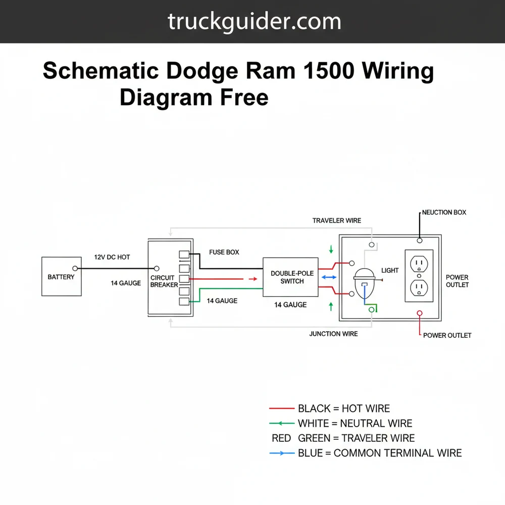
[DIAGRAM_PLACEHOLDER: A detailed 12V DC Automotive Wiring Schematic showing a Power Distribution Center (PDC), a Relay, a Switch, and a Load. Labels include: 12V Hot Wire (Red), Chassis Ground (Black), Trigger Wire (Green), and Fuse (Yellow). The diagram illustrates the flow from the battery through a fuse to a common terminal on a relay.]
In some aftermarket applications or complex relay logic found in the Ram 1500, you might encounter terms like a traveler wire or a common terminal. While these are more frequent in 3-way residential lighting, the logic applies to automotive SPDT (Single Pole Double Throw) relays. The common terminal (Pin 30) is where the main power enters, while the traveler-style logic determines whether power exits through the “Normally Closed” (Pin 87a) or “Normally Open” (Pin 87) terminal.
Step-by-Step Guide to Reading and Implementing the Wiring Diagram
📤 Share
💾 Download
Navigating a schematic dodge ram 1500 wiring diagram free of errors requires a methodical approach. Follow these steps to translate the lines on the page into successful repairs on your vehicle.
- Identify the Power Source: Start at the left or top of the diagram where the battery or fuse box is located. Trace the hot wire (usually indicated in red or a solid bright color) as it leaves the Power Distribution Center. Note the fuse number and amperage rating associated with your circuit.
- Locate the Control Device: Most circuits in a Ram 1500 are interrupted by a switch or a relay. On the schematic, look for the symbol of a switch. If it is a relay-controlled circuit, identify the coil pins (usually 85 and 86) and the switch pins (30 and 87). This is where the voltage is toggled to activate the component.
- Verify Wire Colors and Gauges: Cross-reference the color codes on the schematic with the physical wires in your truck. For example, a “DB/WT” notation means Dark Blue with a White tracer. Use a wire gauge tool if you are unsure of the thickness, especially if you are splicing in a repair section.
- Check the Grounding Point: Every load (light, motor, etc.) must have a path back to the battery. Locate the ground wire on the schematic and find its physical termination point on the truck’s chassis. These are often hidden behind kick panels or under the dashboard.
- Test for Continuity: Use a digital multimeter set to the Ohms or Continuity setting. With the battery disconnected, touch one probe to the beginning of the wire (at the fuse) and the other at the end (at the component). A “beep” or a low resistance reading confirms the wire is intact.
- Measure Operational Voltage: Reconnect the battery and set your meter to DC Volts. With the circuit turned on, check for 12V at the common terminal of the switch or relay. If you see significantly less than 12V, you may have a corroded connection or a “high resistance” short.
- Inspect Connectors for Corrosion: Look for the brass screw or tin-plated terminals inside plastic connectors. Over time, moisture can cause green crust (oxidation) to form, which acts as an insulator and stops the flow of electricity.
For complex computer-controlled circuits, a logic probe is often better than a multimeter. It can quickly show you if a wire is “High” (12V), “Low” (Ground), or pulsing (PWM signal), which is common for modern Ram 1500 headlight dimming and fuel injectors.
To perform these tasks, you will need a basic electrical toolkit:
- ✓ Digital Multimeter (DMM) with high impedance
- ✓ Wire strippers and crimpers
- ✓ Heat shrink tubing and a heat gun
- ✓ DeoxIT or other electronic contact cleaners
Common Issues & Troubleshooting Electrical Faults
📤 Share
💾 Download
The Dodge Ram 1500 is known for a few specific electrical quirks that are easily identified once you have a schematic in hand. One of the most frequent issues involves the Totally Integrated Power Module (TIPM). The TIPM acts as the brain for power distribution, and when it fails, you may see “ghost” symptoms like windshield wipers turning on by themselves or the fuel pump failing to engage.
When troubleshooting, the neutral wire concept is replaced by the chassis ground. A loose ground is the most common cause of intermittent electrical problems. If multiple seemingly unrelated components fail at once—for example, the radio and the interior lights—check the schematic for a shared ground point. If that ground point is loose or rusted, neither circuit will function correctly despite having a perfectly good hot wire feeding them.
Another common issue is a “parasitic draw,” where the battery drains overnight. By using the schematic dodge ram 1500 wiring diagram free of confusion, you can perform a fuse-pull test. You measure the millivolts across the top of each fuse. If a fuse shows a voltage drop while the truck is off, that circuit is pulling power. The schematic will tell you exactly what is on that circuit, allowing you to isolate the faulty module.
Yellow looms and connectors almost always indicate the SRS (Airbag) system. Never probe these wires with a multimeter, as the small amount of current used by the meter to check resistance can accidentally trigger an airbag deployment. Always wait at least 15 minutes after disconnecting the battery before working near yellow-coded wiring.
Best Practices for Durable Electrical Repairs
When you are following a schematic dodge ram 1500 wiring diagram free to perform a permanent fix, the quality of your work determines how long the repair will last. Trucks are subjected to extreme vibrations, heat, and moisture, all of which are enemies of electrical stability.
First, consider the connection method. While “T-taps” and “vampire clips” are popular for their ease of use, they are prone to failure because they cut into the copper strands and expose them to the air. The best practice is to use a “Western Union” splice, solder the connection, and seal it with marine-grade heat shrink tubing that contains an inner adhesive. This creates a waterproof seal that protects the brass screw terminals or crimps from the elements.
When adding aftermarket accessories like off-road lights or winches, never tap directly into an existing circuit unless the schematic shows it has the available capacity. Instead, use the existing schematic to find a “Switched Hot” source to trigger a new relay. This ensures your new high-amperage accessory is fed directly from the battery (using a proper gauge wire and fuse) and only operates when the ignition is on.
Maintenance is also key. Periodically check the main battery terminals and the ground straps connecting the engine block to the frame. A light coating of dielectric grease on the common terminal of external sensors can prevent moisture intrusion. Remember that a schematic is only as good as the physical connections it represents; even the most accurate diagram cannot overcome a corroded wire hidden inside a plastic loom.
Conclusion: Mastering Your Ram 1500 Electrical System
Mastering the electrical system of your truck starts with a high-quality schematic dodge ram 1500 wiring diagram free of inaccuracies. By understanding the relationship between the hot wire and the ground wire, and by respecting the specific voltage and gauge requirements of each circuit, you transform from a frustrated owner into a capable DIY technician.
Electrical work requires patience and a systematic approach. By tracing circuits from the power source through the common terminal of switches to the final load, you can eliminate the guesswork that leads to “parts cannon” repairs. Whether you are cleaning a brass screw terminal or diagnosing a complex PCM communication error, the schematic is your roadmap. With the right tools and the knowledge contained in this guide, you can keep your Dodge Ram 1500 on the road and ensure its electrical systems are as reliable as its HEMI engine.
In the world of automotive repair, information is power. Having a clear diagram allows you to visualize the invisible flow of electrons, making even the most daunting wiring harness manageable. Stay safe, double-check your connections, and always refer back to your schematic before making any permanent changes to your vehicle’s wiring.
Frequently Asked Questions
Where is the Dodge Ram 1500 fuse box located?
The primary Power Distribution Center is located under the hood, usually on the driver’s side near the battery. It contains the main fuses and relays. A secondary fuse panel may be found inside the cabin, typically on the side of the dashboard accessible when the driver’s door is open.
What does a schematic dodge ram 1500 wiring diagram free show?
This diagram displays the flow of electricity from the power source to various components. It highlights color-coded wires, fuse ratings, and connection points. It specifically shows how the hot wire interacts with switches and relays to power the truck’s lights, ignition system, sensors, and interior electronics safely.
How many wires does the RAM 1500 headlight connector have?
Most standard RAM 1500 headlight connectors use three to four wires. This includes a ground wire, a low-beam lead, and a high-beam lead. Some models utilize a traveler wire setup for multi-function signal switching, ensuring the computer can monitor bulb integrity and manage the daytime running light functions.
What are the symptoms of a bad TIPM in a Dodge Ram?
A failing Totally Integrated Power Module often causes erratic electrical behavior. Symptoms include fuel pumps running constantly, headlights flickering, or power windows failing. Checking the common terminal on the TIPM connectors can help determine if the module is distributing power correctly or if a circuit is internally shorted.
Can I troubleshoot Dodge Ram wiring issues myself?
Yes, with a schematic dodge ram 1500 wiring diagram free, a DIYer can handle many repairs. By tracing the hot wire from the fuse to the component, you can find breaks. While automotive systems use a chassis return instead of a traditional neutral wire, the principles of continuity remain the same.
What tools do I need for Dodge Ram electrical work?
You will need a digital multimeter to test for voltage and resistance. A test light is helpful for quick circuit checks. Wire strippers, crimpers, and heat-shrink tubing are essential for making permanent repairs. Ensure you have the correct schematic to identify which pin belongs to the common terminal.