Dodge Ram Dashboard Symbols – Exhaustive Meanings, Diagnostics & Reset Procedures (1500/2500/3500)
The automotive dashboard has evolved from a passive display of analog information into a sophisticated Human-Machine Interface (HMI) functioning as the primary output for the vehicle’s Controller Area Network (CAN) bus. In the context of the Ram truck lineup—spanning the DS (Generation 4) and DT (Generation 5) platforms—the instrument cluster is no longer merely a set of gauges;

it is a “Driver Information Digital Cluster” (DIDC) that aggregates telemetry from over 30 distinct control modules, including the Powertrain Control Module (PCM), Body Control Module (BCM), and Drivetrain Control Module (DTCM).
This report provides an exhaustive technical breakdown of the symbology, trigger logic, and diagnostic protocols for Ram 1500, 2500, and 3500 trucks. It moves beyond superficial icon identification to analyze the electromechanical root causes of warnings, particularly distinguishing between the gasoline architectures (3.6L Pentastar / 5.7L Hemi) and the complex hydro-chemical monitoring required by the 6.7L Cummins Turbo Diesel platform.
Interface Architecture and Logic
The logic governing Ram dashboard symbols follows a strict prioritization algorithm designed to manage driver cognitive load. Warnings are filtered through the Gateway Module (often the BCM or a dedicated Security Gateway in 2018+ models) which determines whether a signal from a peripheral sensor (e.g., a wheel speed sensor) warrants a visual interruption in the cluster.
Understanding this architecture is critical for diagnostics. A symbol on the dashboard is rarely a standalone indicator; it is the final link in a chain of data validation. For instance, the illumination of the Electronic Stability Control (ESC) light is not triggered directly by the wheels, but by the ABS module computing a variance between the Steering Angle Sensor (SAS) and the Yaw Rate Sensor, then broadcasting a request to the cluster to illuminate the icon.
Dodge Ram Dashboard Decoder
Don’t panic. Understand the language of your truck. From the infamous “Red Lightning Bolt” to the Check Engine light, we visualize the data you need to decide: Drive on or Stop immediately?
The Hierarchy of Urgency
Not all lights are created equal. Ram trucks use a universal “Traffic Light” logic to categorize system feedback. Understanding this split is your first line of defense.
Red: Critical Failure
Potential for catastrophic damage or safety hazard. Stop driving immediately.
Amber: Warning
System malfunction or maintenance required. Driveable, but schedule service.
Green/Blue: Information
System is active (e.g., Headlights, 4WD High, Cruise Control).
Distribution of Dashboard Symbols
Based on standard Gen 4/5 Ram Instrument Clusters
The Electronic Throttle Control (ETC)
Commonly known as the “Red Lightning Bolt,” this is the most feared and misunderstood symbol on Ram trucks. It indicates a disconnect between your gas pedal and the engine.
Troubleshooting Workflow
Most Reported Warning Lights
Based on user reports from RamForum and RepairPal (2023-2024).
Estimated Repair Costs
Comparison of DIY fix (parts only) vs Professional Shop repair.
Quick Reference Glossary
Common symbols found on Gen 4 (2009-2018) and Gen 5 (2019+) Ram 1500s.
Tire Pressure (TPMS)
Solid means low pressure. Flashing means sensor fault. Ram tires usually require 35-40 PSI (Light loads).
Engine Temp
Coolant is overheating (>240°F). Check for leaks or stuck thermostat. Stop engine immediately to avoid warping heads.
ABS Warning
Anti-lock Brake System is disabled. Normal braking works, but no skid protection. Often caused by wheel speed sensors.
© 2026 TruckGuider Infographics
The Hierarchical Logic of Visual Alerts (Color Theory)
The Ram instrument cluster utilizes a standardized, Federal Motor Vehicle Safety Standards (FMVSS) compliant color-coding system. However, Ram engineers have integrated specific logic states unique to the brand’s heavy-duty heritage.
The “Bulb Check” Verification Protocol
Upon every ignition cycle (turning the key to ON/RUN or pressing Start without the brake), the cluster initiates a “Bulb Check” or “Segment Check” sequence.
- Mechanism: The BCM commands all hard telltales (LED icons) to illuminate and the digital display to pixelate for 4 to 8 seconds.
- Diagnostic Utility: This is the primary verification step for purchase inspections. If a critical light (such as the Check Engine or Airbag light) fails to illuminate during this phase, it indicates either a hardware failure (burnt LED) or intentional tampering (tape over the LED or disabled circuit) to hide active faults.
- POST Sequence: Following the bulb check, the modules perform a Power-On Self-Test (POST). Lights should extinguish sequentially. Any light remaining on indicates an active, confirmed fault code.
Alert Classification Matrix

The following table details the operational hierarchy of Ram dashboard indicators.
| Color | Category | System State | Driver Action Required | Examples |
| Red | Critical / Emergency | System Failure or Safety Threat | Immediate Stop. Continued operation will result in catastrophic mechanical failure or safety compromise. | Oil Pressure, Engine Temp, Airbag (SRS), Door Open (in motion), Electronic Throttle Control (Lightning Bolt). |
| Amber / Yellow | Caution / Maintenance | Parameter Out of Range | Service Soon. Vehicle is operational but relying on backup values or lacking emissions compliance. | Check Engine (MIL), TPMS, ABS, Water in Fuel, DPF Full. |
| Green | Active Status | System Functional | None. Confirms feature engagement. | Turn Signals, Headlights, Cruise Control Set, Eco Mode. |
| Blue | High Priority Status | High Intensity Output | None. Indicates blinding potential to others. | High Beam Headlights. |
| White | Standby / Information | System Ready / Armed | None. Feature is available but not currently intervening. | Adaptive Cruise Ready, Lane Sense Standby. |
Critical Powertrain Warnings: Gasoline Platforms (Hemi V8 / Pentastar V6)
The gasoline powertrains in the Ram 1500 (and gas 2500s) utilize specific symbology related to the “Drive-by-Wire” and Evaporative systems.
Electronic Throttle Control (ETC) – The “Red Lightning Bolt”

The ETC light, depicted as a red lightning bolt between inverted parentheses, is arguably the most feared and misunderstood symbol in the Ram ecosystem.
System Mechanics
Modern Ram trucks do not use a physical cable to connect the gas pedal to the engine. Instead, they use a redundant electronic loop:
- Accelerator Pedal Position (APP) Sensor: Contains two internal potentiometers that send dual voltage signals to the PCM to cross-verify driver intent.
- Throttle Body: An electric servo motor actuates the butterfly valve.
- Throttle Position Sensor (TPS): Reports the actual angle of the valve back to the PCM.
Fault Logic and “Limp Mode”
The Lightning Bolt illuminates when the PCM detects a Voltage Correlation Failure (e.g., Code P2135). If Signal A and Signal B from the pedal do not match, or if the commanded throttle angle differs from the actual angle by a set variance, the system assumes a safety risk.
- Limp Mode: To prevent a runaway engine, the PCM defaults to “Limp Mode.” The throttle plate is locked at a high idle (or very limited opening). The driver will experience zero throttle response, rough idling, and a limitation of RPMs.
- The 4WD Correlation: In many Ram models, an ETC fault triggers the immediate disablement of the 4WD system and Traction Control. This causes the “Service 4WD” and “Traction Control Off” lights to illuminate alongside the lightning bolt. This is a fail-safe strategy, not a simultaneous triple component failure.
Diagnostic and Repair Protocols
- The “Relearn” Procedure: Before component replacement, a soft reset can be attempted. This typically involves: 1) Key ON (Engine OFF), 2) Slowly depress pedal to floor and release slowly, 3) Key OFF. This recalibrates the potentiometer range.
- Common Failures: The most frequent hardware failures are stripped plastic gears within the throttle body servo or carbon buildup preventing the plate from closing. The pedal assembly is the second most common failure point.
Malfunction Indicator Light (MIL) – “Check Engine”
The amber engine silhouette represents the OBD-II emissions monitoring system.
Solid vs. Flashing Logic
- Solid Illumination: A sensor reading is out of range (e.g., O2 sensor, Mass Air Flow), but the engine management can compensate using “fuel trim” adjustments.
- Flashing Illumination: Indicates a severe active misfire (P0300 series). Unburnt fuel is being dumped into the exhaust stream where it will ignite in the catalytic converter, causing superheating (2000°F+) and substrate meltdown. Driver Action: Reduce load immediately.
The “Loose Gas Cap” Phenomenon
Ram trucks feature a dedicated “Gas Cap” indicator or message that often precedes a hard Check Engine code.
- Mechanism: The Evaporative Emissions (EVAP) system performs a vacuum decay test on the fuel tank while the vehicle is parked or cruising. If vacuum is lost, it assumes a leak.
- Resolution: Tightening the cap does not immediately reset the light. The vehicle must undergo multiple “drive cycles” (cold start -> warm up -> highway cruise) for the PCM to run the integrity test again and clear the message. If the message persists, the EVAP Purge Valve or Vent Valve are common failure points.
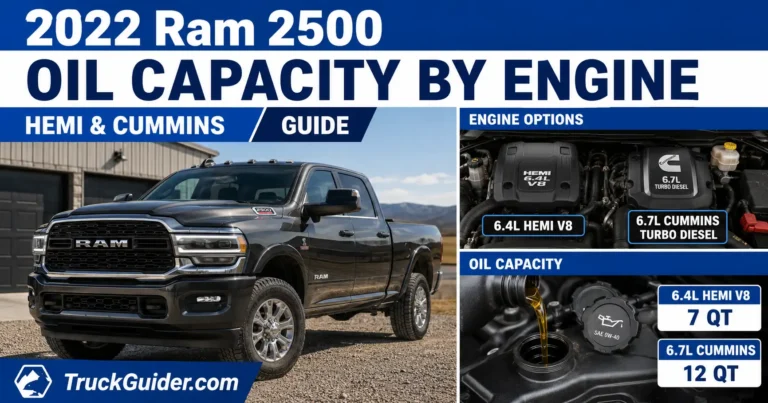
Lubrication and Thermal Management
- Oil Pressure (Red Oil Can): Monitors the main oil galley. In 5.7L Hemi engines, the oil pressure sensor (transducer) located above the oil filter is a known failure point. It often fails “high” (pegged at 100 PSI) or “low” (0 PSI). However, a reading of 0 PSI must always be treated as a pump failure until verified with a mechanical gauge.
- Coolant Temperature: Ram trucks utilize Active Grille Shutters to manage aerodynamics and thermal warmup. A fault in the shutter motor can trigger temperature warnings if they fail in the “closed” position while towing.
Diesel-Specific Monitoring: Cummins 6.7L & EcoDiesel 3.0L
The instrument clusters in Ram 2500/3500 HD trucks contain a distinct set of symbols related to the elaborate chemical processing plant located in the exhaust system: the Aftertreatment System.
Water in Fuel (WIF) Indicator
Diesel fuel is hygroscopic (absorbs water). Modern Common Rail Injection systems operate at pressures exceeding 25,000 PSI. At these pressures, water acts as a cutting torch, destroying injector tips and the CP4/CP3 injection pump.
- Symbol: A red fuel pump icon with a water droplet.
- Sensor Logic: A conductivity probe is located in the fuel-water separator filter (chassis or engine mounted). When water (which conducts electricity better than diesel) bridges the probe, the circuit closes, triggering the light and Code P2269.
- Mandatory Action: The driver must immediately stop and drain the separator.
- Procedure:
- Locate the yellow drain valve on the fuel filter housing (often accessed through the driver-side wheel well on HD models).
- Open valve to allow gravity drain until clean diesel flows.
- Close valve. Cycle ignition to prime. Ignoring this light is the leading cause of complete fuel system failure in Ram diesels..
Diesel Particulate Filter (DPF) Status
The DPF traps soot (particulate matter). It must be cleaned via “Regeneration” (oxidizing soot into ash at 1100°F).
- Symbol: Amber exhaust muffler with dots.
- Status Hierarchy:
- No Light: System is functioning; passive regeneration (during highway driving) is keeping soot load low.
- Solid Amber: DPF is full. Passive regen is insufficient. Action: Drive at highway speeds (uninterrupted) for 20-45 minutes to induce active regen.
- Flashing Amber: DPF is critically full. Engine power may be reduced. Action: Perform “Parked Regeneration” if equipped, or seek immediate service.
- Stop Engine / Service Exhaust: Soot load has exceeded the safety threshold (e.g., 100% full). The truck enters “Derate” (Limp Mode) to prevent excessive backpressure from blowing turbo seals. Dealer service is required to force induction or replace the filter.
Diesel Exhaust Fluid (DEF) / SCR
The Selective Catalytic Reduction (SCR) system uses DEF (urea) to scrub NOx.
- Inducement Logic: The EPA mandates that if DEF is empty, the vehicle cannot operate. Ram implements a countdown: “500 miles to speed limit.” If the counter hits zero, the truck enters a 5 MPH Max Speed inducement mode. This is not a mechanical failure but a software lockout.
Chassis Dynamics and Safety Systems
Tire Pressure Monitoring System (TPMS)
Ram trucks use Direct TPMS with battery-powered sensors transmitting via RF (315 MHz or 433 MHz) to the Radio Frequency Hub (RFH).
- Symbol: Amber tire cross-section with exclamation point.
- “Light Load” Switch (HD Models): Ram 2500/3500s often run high pressures (80 PSI) for load rating. When empty, 80 PSI yields a harsh ride. The “Light Load” button on the center stack alters the TPMS threshold in the BCM, allowing drivers to lower rear tires to ~60 PSI for comfort without triggering the warning light.
- Tire Fill Alert (Gen 5): On newer models, when inflating a tire, the horn will chirp automatically when the set pressure is reached, allowing a single person to inflate tires without checking a gauge repeatedly.
- Flashing Warning: A TPMS light that flashes for 75 seconds and then stays solid indicates a System Malfunction (usually a dead sensor battery or failed RF Hub), not low pressure.
Anti-Lock Braking (ABS) and Stability Control
The ABS module monitors wheel speed sensors at all four corners.
- Correlation: If the ABS light is on, the Traction Control (ESC) light will almost always be on as well, because ESC cannot function without ABS data.
- Cruise Control Impact: An ABS fault will universally disable Cruise Control, as the system cannot guarantee safe deceleration.
- Service Electronic Braking System: This message typically points to a failure in the Hydraulic Control Unit (HCU) or a specific wheel speed sensor wire break (common on lifted trucks where wires are stretched).
Advanced Driver Assistance Systems (ADAS) – Gen 5 (DT)
The 2019+ Ram 1500 (DT) platform introduced Level 2 autonomous features, creating a new visual vocabulary in the instrument cluster.
Hands-Free Active Driving Assist (ADA)
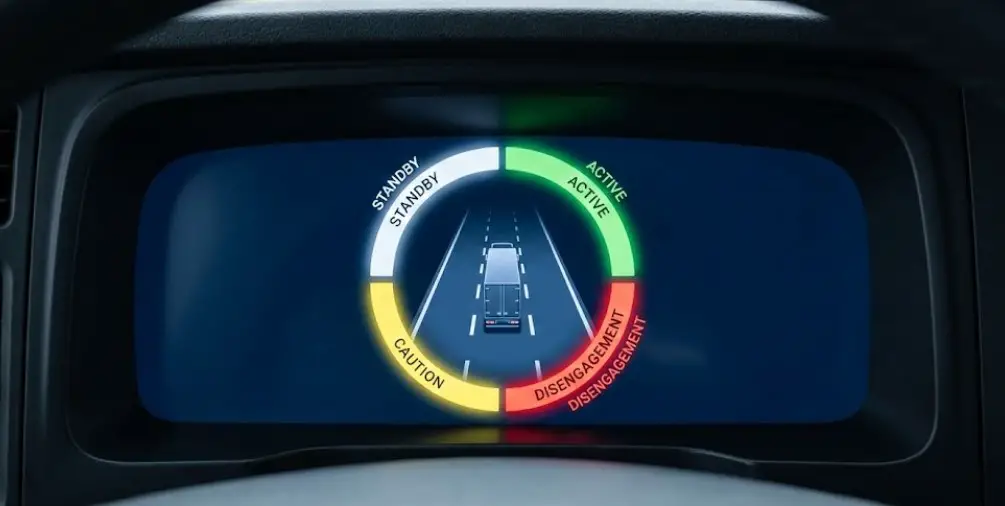
Located in the central digital display, this system uses a color-coded halo to communicate the status of the semi-autonomous pilot.
| Status Color | Meaning | System Behavior |
| White | Standby | System is available but not currently controlling steering/speed. |
| Green | Active | System is actively steering and maintaining speed/gap. |
| Yellow | Fault / Caution | System limits reached (e.g., lane markings lost) or driver attention required. |
| Red (Flashing) | Disengagement | Critical alert. Driver must take control immediately. Often triggers braking jolt. |
Lane Sense and Lane Keep Assist
- Visual: Lane outlines appear on the cluster road display.
- Grey: Lane lines not detected.
- White: Lane lines detected; system armed.
- Solid Yellow: Vehicle is drifting near a lane marker.
- Flashing Yellow: Vehicle is crossing a lane marker; Electric Power Steering (EPS) will apply torque to correct.
Diagnostic Protocols and Hidden Menus
Ram trucks contain “Easter Egg” diagnostic modes that allow owners to view raw sensor data without a scan tool.
Instrument Cluster Self-Test (Actuator Test)
This procedure verifies if a gauge needle is physically stuck or if the cluster LED is burnt out.
- Procedure (Gen 4/Classic):
- Hold the Trip Reset button (odometer stem).
- Turn ignition to ON/RUN (do not start engine).
- Continue holding until the odometer displays “Check” or “Test” (approx. 5-8 seconds).
- Result: The cluster will sweep all gauges from 0% to 100%, light every LED segment, and test the chime. This confirms cluster health versus signal health.
Uconnect Engineering / Dealer Mode
The central infotainment screen (8.4″ or 12″) hosts a backend technician menu.
- Access (Gen 4 / Uconnect 3 & 4): Hold the Driver “Temp Up” and “Temp Down” buttons (physical buttons) simultaneously for 5+ seconds.
- Access (Gen 5 / Uconnect 5): Hold the top-left and top-right corners of the touchscreen for 10+ seconds.
- Data Utility: This mode allows viewing of:
- GPS Satellite Strength (diagnosing navigation drifts).
- LTE Modem Status (diagnosing connected services issues).
- Raw Voltage inputs.
- Software Versioning (critical for determining if an Over-the-Air update is pending).
Reset Procedures and Maintenance
Resetting the “Check Engine” Light (Without Scanner)
While a scanner is the correct tool, the “Battery Disconnect” method is a common field tactic.
- Procedure: Disconnect the negative battery terminal. Wait 15-20 minutes. Some technicians touch the disconnected negative cable to the positive terminal (capacitive discharge) to drain all module capacitors instantly.
- Warning: This resets the PCM’s “Volatile Memory.” It clears the error code and the Emissions Readiness Monitors. The truck will display “Not Ready” at a smog check until a full drive cycle is completed. If the mechanical fault persists, the light will return once the monitor runs.
Oil Change Reset
- Method: Turn ignition to ON (Engine Off). Depress the accelerator pedal slowly three times within 10 seconds. Turn ignition OFF. This resets the duty-cycle algorithm.
Frequently Asked Questions (Deep Analysis)
Q: Why does my “Service 4WD” light come on when my “Lightning Bolt” throttle light is on?
This is a safety correlation, not a dual failure. The 4WD system relies on torque management data from the engine. If the throttle control is irrational (Lightning Bolt), the 4WD module cannot safely predict engine torque, so it disables the 4WD system to prevent drivetrain bind-up or damage. Fixing the throttle body usually clears the 4WD light.
Q: Can I drive with the “Lightning Bolt” light on?
Generally, no. The vehicle will likely be in “Limp Mode” with severely restricted acceleration. Merging onto highways is dangerous. The vehicle is designed to be driven only as far as a safe parking spot.
Q: My TPMS light flashes for a minute then stays solid. Air pressure is fine. What is it?
A: This specific pattern (Flash 75s -> Solid) is the universal code for System Malfunction. It almost always indicates a dead battery in one of the tire sensors (sensor lifespan is 7-10 years) or a fault in the RF Hub receiver.
Q: What is the difference between the “Exhaust Filter Full” message and the “Service Exhaust System” message?
“Filter Full” is a maintenance prompt requiring a regeneration drive. “Service Exhaust System” indicates a hardware fault (e.g., bad NOx sensor, DEF pump failure) or that the filter is so full it can no longer be regenerated safely by driving. The latter requires dealer intervention.
Conclusion
The dashboard of a modern Dodge Ram is a complex visualization of the vehicle’s neural network. For the owner, the critical takeaway is the interpretation of urgency: Red demands cessation of driving to save the machine; Amber requests scheduled attention.
The transition from the Gen 4 (DS) to the Gen 5 (DT) platform has shifted diagnostics from simple resistance-based sensors to digital modules communicating via high-speed CAN bus. While this increases the precision of warnings—allowing for features like specific tire pressure readouts and autonomous lane centering—it also means that simple dashboard symbols often represent complex, multi-module decisions.
By utilizing the “Bulb Check” to verify cluster integrity, understanding the “Limp Mode” triggers of the Electronic Throttle Control, and respecting the distinct hydro-chemical needs of the diesel aftertreatment systems, operators can ensure the longevity and reliability of these high-performance truck platforms.

![2013 Ram 1500 Headlight Bulb Replacement: Complete Specs Guide [2026]](https://truckguider.com/wp-content/uploads/2026/03/2013-ram-1500-headlight-bulb-replacement-featured.webp)
![2020 Ram 1500 Oil Capacity & Type: Complete Engine Guide [2026]](https://truckguider.com/wp-content/uploads/2026/03/2020-ram-1500-oil-capacity-featured-768x403.webp)
![2015 Ram EcoDiesel Problems: Common Failures & Recalls [2026]](https://truckguider.com/wp-content/uploads/2026/03/2015-ram-ecodiesel-problems-featured.webp)