Heater Core Hose Diagrams, Routing, and Repair Strategies – Ultimate Technical Guide 2026
The automotive internal combustion engine is a heat engine that operates at a thermal efficiency of roughly 30% to 40%. The remaining energy is dissipated as waste heat, primarily through the exhaust system and the engine cooling system. Within this cooling architecture, the heater core circuit occupies a unique and often underestimated role. While its primary consumer-facing function is to provide cabin comfort by acting as a liquid-to-air heat exchanger for the HVAC (Heating,
Ventilation, and Air Conditioning) system, structurally, it functions as a secondary bypass circuit that is essential for proper engine warm-up, thermostat operation, and air-bleeding dynamics.
For technicians and vehicle owners alike, the heater core plumbing—comprising supply hoses, return hoses, control valves, and quick-connect fittings—represents a common failure point that can lead to catastrophic engine damage if misdiagnosed. A simple leak in a heater hose quick-disconnect fitting on a highway can result in rapid coolant loss, cylinder head warping, and total engine failure.
Therefore, understanding the precise routing, flow direction, and connection points of these hoses is not merely a matter of restoring cabin heat; it is a matter of preserving the mechanical integrity of the vehicle.
This report serves as a definitive reference for the identification, diagnosis, and repair of heater hose assemblies on the most prevalent light-duty truck platforms in North America: the Chevrolet Silverado/GMC Sierra (GMT800/GMT900/K2XX), the Ford F-150 (12th and 13th Generation), the Ram 1500 (DS/DT), and the Toyota Tundra (XK50).
By synthesizing technical service bulletins, expert repair protocols, and component engineering data, we provide a granular analysis of “heater core hose diagrams” that translates static schematic data into actionable physical repair strategies.
Heater Core Hose Diagrams
Navigating the coolant loop: Diagnostics, flow logic, and repair data for truck owners.
The Critical Coolant Loop
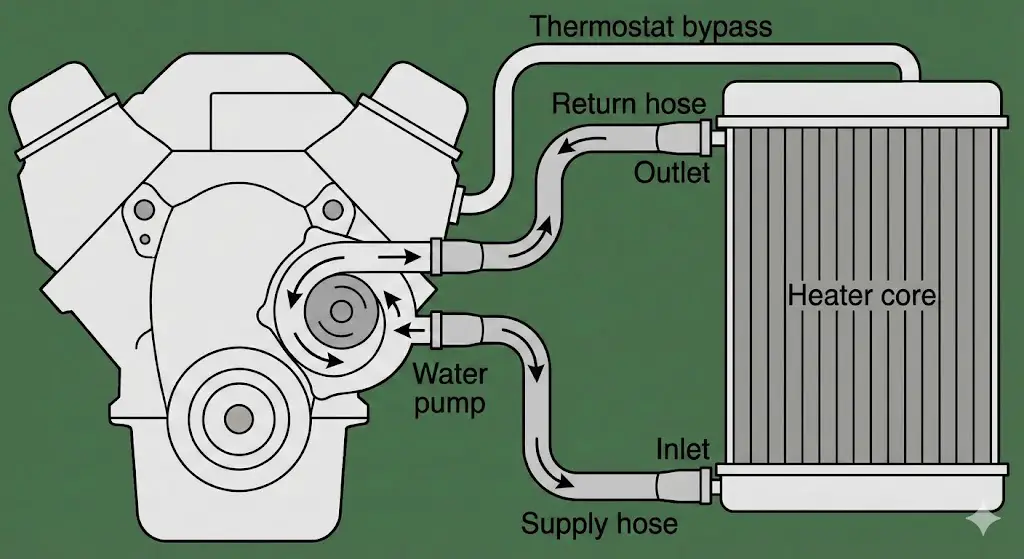
The heater core hose system is a bypass loop within your vehicle’s cooling system. It diverts hot coolant from the engine block, pushes it through the firewall, and circulates it through the heater core—a mini radiator inside your dashboard—before returning it to the water pump. Understanding this flow direction is critical for installing flush kits, diagnosing “no heat” conditions, and identifying leaks.
System Flow Visualization
Conceptual flow of hot coolant from the engine to the cabin and back.
Common Failure Points
Based on service records for vehicles >100k miles.
Diagnosing Clogs via Temperature
A healthy system maintains a small temperature drop across the core. A clogged core shows a drastic drop at the outlet hose.
Repair Cost Comparison
Heater core replacement is labor-intensive (dashboard removal). Hose replacement is affordable and DIY-friendly.
Diagnostic Checklist: Is it the Hose or the Core?
Foggy Windows
Greasy film on inside windshield indicating core vapor leak.
Sweet Smell
Distinct maple syrup odor inside the cabin (Antifreeze).
Wet Floorboard
Coolant pooling under the passenger side carpet.
Cold Air at Idle
Heat works while driving but cools at stoplights (Low Coolant/Air Pocket).
Troubleshooting Logic Flow
Follow this logic path to determine if you need to flush the system, replace a hose, or replace the entire heater core.
Look for external leaks at hose clamps or water pump weep hole. Top off and bleed air.
Feel the inlet and outlet hoses at the firewall once engine is warm.
One Cold? = Clogged Core
TruckGuider.com © 2026 – Automotive Diagnostics Series
Fundamentals of Automotive Hydronics and Thermodynamics
To accurately interpret a heater hose diagram or diagnose a flow issue, one must possess a foundational understanding of the fluid dynamics governing the engine cooling loop. The heater core is not a passive reservoir; it is a dynamic circuit driven by the pressure differentials created by the water pump.
The Physics of Coolant Flow and Pressure Differentials
The movement of coolant through the heater core is driven by the mechanical energy of the water pump. In a standard centrifugal water pump design, the impeller creates a zone of high pressure at its periphery (outlet) and a zone of low pressure at its center (inlet/suction).
- The Supply Side (High Pressure): The heater supply hose typically originates from a high-pressure port on the engine. This port is located after the water pump impeller but before the thermostat restriction in many bypass-style systems, or directly from the cylinder head or intake manifold where coolant is hottest and under significant pressure. The objective is to divert a stream of hot coolant to the heater core immediately as the engine warms up, often bypassing the radiator thermostat to provide rapid cabin heat.
- The Return Side (Suction/Low Pressure): The return hose carries thermal-energy-depleted coolant back to the engine. To ensure flow, this hose must terminate at a low-pressure zone, typically the suction side of the water pump or the lower radiator hose inlet. The pressure differential ($ \Delta P $) between the supply tap on the cylinder head/block and the suction port on the pump is what drives the fluid through the restrictive tubes of the heater core.
Insight: This pressure differential is critical when installing auxiliary heaters or bypass loops. If a technician mistakenly tees a heater return line into a high-pressure zone (like the upper radiator hose), the $ \Delta P $ approaches zero, resulting in flow stagnation and a “no heat” condition despite the system being full of coolant.
Heater Core Flow Direction: The Inlet vs. Outlet Debate
A persistent source of confusion in automotive repair is the identification of inlet and outlet ports at the firewall. While a heater core—being a simple radiator—can theoretically flow in either direction, directional adherence is critical for three primary reasons:
- Air Evacuation (The “Bottom-Up” Rule): Air is less dense than water and naturally rises. Automotive engineers typically design the heater core flow path so that the inlet is at the bottom and the outlet is at the top. As the heavier coolant enters the bottom, it displaces air upwards and out through the return hose, effectively self-bleeding the core. If the hoses are reversed (top-in, bottom-out), the rushing water can cascade over trapped air pockets, creating a permanent air lock that reduces heat output and causes a gurgling “waterfall” sound behind the dashboard.
- Sediment Flushing: Coolant systems accumulate sediment (casting sand, rust scale, precipitated silicates). In a standard flow, this sediment may settle in the bottom tank. If the flow is reversed during operation, sediment may be forced into the narrow capillary tubes of the core, causing blockages. Conversely, when servicing a clogged core, technicians intentionally reverse the flow (back-flushing) to dislodge this debris.
- Heater Control Valves: Older vehicles and some modern applications use a directional flow valve to stop hot coolant from entering the cabin when the A/C is on. These valves often operate as check valves or rely on fluid pressure to assist the sealing mechanism. Reversing the hoses can force these valves open or cause them to chatter.
Electrochemical Degradation (ECD) and Hose Failure
Modern heater hose failure is rarely a result of simple abrasion; it is increasingly caused by Electrochemical Degradation (ECD). The cooling system acts as a battery, with the coolant serving as the electrolyte and the various metals (aluminum head, iron block, brass core, copper radiator) acting as electrodes.
As coolant additives (corrosion inhibitors) break down over time, the coolant becomes conductive. An electrical charge creates localized electrolysis at the junction where the rubber hose meets the metal fitting. This reaction generates micro-cracks within the EPDM (Ethylene Propylene Diene Monomer) rubber tube, often referred to as “striations.”
Insight: ECD is insidious because the hose looks new on the outside. The damage is entirely internal. A hose suffering from ECD will feel soft or “spongy” when squeezed near the clamp, or conversely, may create a “crunching” sound if the inner reinforcement has become brittle. This phenomenon drives the recommendation to replace hoses and clamps proactively every 5-7 years or 100,000 miles, regardless of visual appearance.
General Architecture of Heater Hose Routing Diagrams
Before diving into vehicle-specifics, we must define the standard symbology and architectural logic used in “heater core hose diagrams.” Since we are describing these visually, we will use a “Node-Edge” topology description method.
The Standard V-Configuration Diagram
In a V-style engine (V6, V8), which powers the majority of the trucks in this report, the heater hoses typically route from the front of the engine (water pump area) to the rear of the engine bay (firewall).
- Node A (Source): Water Pump Housing or Intake Manifold Crossover.
- Edge 1 (Supply Hose): Runs along the top of the passenger-side valve cover or tucked under the intake manifold plenum.
- Node B (Firewall Inlet): The heater core pipe protruding through the firewall.
- Node C (Firewall Outlet): The adjacent heater core pipe.
- Edge 2 (Return Hose): Runs parallel to the supply hose or diverges to meet the radiator loop.
- Node D (Sink): Water Pump Suction Port or Lower Radiator Hose Tee.
Visualizing Connections: Quick Connects vs. Barb Clamps
The diagram is complicated by the connection method.
- Traditional Barb & Clamp: Used on older trucks and arguably the most reliable. The hose slides over a flared metal tube and is secured by a worm-gear or constant-tension spring clamp.
- Quick Connect (QC) Fittings: The industry standard for the last two decades. These are plastic or metal couplings that snap onto a beaded tube. They utilize internal O-rings for sealing and plastic tabs for retention.
- Pros: Rapid assembly on the production line.
- Cons: High failure rate in service due to plastic embrittlement; difficult to disconnect without specialized tools.
Vehicle-Specific Analysis: Chevrolet Silverado / GMC Sierra (GMT800/900/K2XX)
The General Motors truck platform, particularly those equipped with the LS-based Vortec engines (4.8L, 5.3L, 6.0L, 6.2L), represents one of the largest vehicle populations in North America. The heater hose arrangement on these engines is distinct due to the integrated water pump design.
The LS Engine Water Pump Architecture
The defining feature of the LS cooling system is the water pump, which serves as the central manifold for the entire cooling circuit. Unlike older Small Block Chevy engines where heater hoses connected to the intake manifold, the LS pump houses both the supply and return ports on the pump casting itself.
Port Identification and Flow Direction
On a standard Gen III/IV LS truck water pump (viewed from the front of the vehicle):
- Location: The heater ports are located on the passenger side of the water pump, vertically aligned.
- The Supply Port (Outlet): This is the smaller, lower port (typically 5/8″ diameter). It ejects pressurized hot coolant.
- The Return Port (Inlet): This is the larger, upper port (typically 3/4″ diameter). It receives cooled coolant returning from the heater core.
- Implication for Diagrams: When tracing hoses on a Silverado, the hose connected to the bottom fitting on the water pump flows toward the firewall. The hose connected to the top fitting on the water pump flows away from the firewall.
Firewall Connections and the Quick Connect Plague
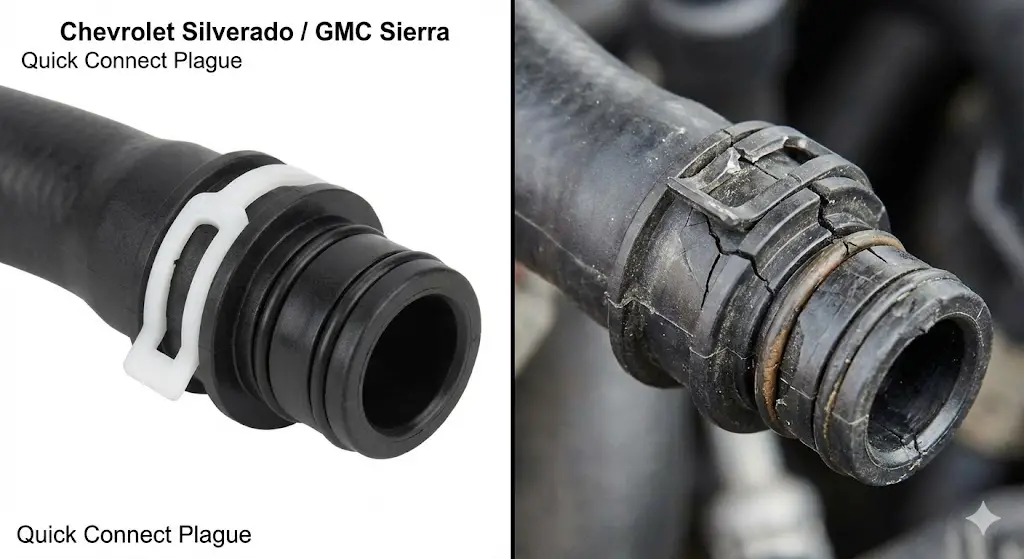
The connection at the firewall is the single most common failure point in the Silverado heating system. GM utilizes a plastic quick-disconnect fitting (Part #800-409 typically) that snaps onto the heater core tubes.
- Failure Mechanism: The plastic body of the connector sits inches away from the exhaust manifold. Over years of thermal cycling, the plastic becomes brittle. Vibration causes the internal O-rings to flatten or the plastic locking tabs to shear off. A common scenario is a connector snapping off entirely during a routine hose inspection, spraying coolant over the hot engine.
- Removal Strategy: The removal requires a specific disconnect tool (like Lisle 37000 or similar). The tool is a hinged plastic or metal sleeve that slides into the connector to depress the internal tangs.
- Warning: Using screwdrivers or picks often gouges the aluminum heater core tube. If the tube is scratched deeply, the new O-ring will not seal, necessitating a massive dashboard-out repair to replace the heater core.
The “Y-Pipe” Assembly for Auxiliary Heat
Models equipped with rear heating (Suburbans, Tahoes, and Crew Cab Silverados) utilize a complex heater hose assembly featuring a plastic “Y” junction.
- The Weak Link: This Y-junction splits the flow between the front heater core and the rear lines running under the chassis. It is manufactured from glass-filled nylon. Like the firewall connectors, this Y-pipe is prone to stress cracking along the mold seams.
- Repair Insight: Many technicians replace the entire molded rubber assembly with a constructed assembly using brass tees and high-grade silicone hose to permanently eliminate the plastic failure point.
Step-by-Step Hose Replacement (5.3L Vortec)
Table 1: Tool and Part Requirements for Silverado 5.3L Heater Hose Repair
| Component | Specification | Notes |
| Disconnect Tool | 3/4″ and 5/8″ Hinged Tool | Mandatory for firewall removal. |
| Hose Material | EPDM Class D1 or D2 | OEM or Gates Green Stripe recommended. |
| Coolant | Dex-Cool (OAT) | Do not mix with green IAT coolant (sludge risk). |
| Clamps | Constant Tension Spring | Re-use OEM if spring rate is good, otherwise replace. |
- Drain Coolant: Drain approximately 2 gallons of coolant via the radiator petcock to lower the level below the heater core.
- Disconnect at Water Pump: Use remote-access hose clamp pliers to compress the spring clamps on the water pump ports. Slide clamps back and twist hoses to break the seal.
- Disconnect at Firewall:
- Spray the quick connect fitting with penetrating oil or silicone spray.
- Insert the disconnect tool into the plastic fitting.
- Push the tool in while pulling the hose out. A distinct “click” indicates release.
- Tip: If the plastic is extremely brittle, it may crumble. Have a pick ready to fish out broken plastic pieces and O-rings from the metal pipe.
- Install New Assembly: Coat the heater core tubes with fresh coolant or dielectric grease. Push the new quick connect fittings on until they click audibly. Tug firmly to verify the lock.
- Bleeding: Fill with Dex-Cool. Run engine at 2500 RPM. The LS engine is generally self-bleeding, but using a funnel to raise the fill point helps.
Vehicle-Specific Analysis: Ford F-150 (5.0L Coyote & 3.5L EcoBoost)
The Ford F-150 presents a bifurcated landscape for heater hose diagrams. The 5.0L V8 follows a somewhat traditional layout, while the 3.5L EcoBoost introduces significant complexity due to the turbocharger cooling loop integration.
The 5.0L Coyote V8 Layout
The 5.0L “Coyote” engine heater hoses are notorious for a specific failure point: the “T-Connector” on the upper hose assembly.
The DR3Z-8566-A / Heater Outlet T-Connector
On the 5.0L, the heater return hose does not run directly to the water pump alone. It connects to a “T” junction that also integrates the thermostat bypass and the reservoir return.
- The Failure: The O-ring inside this T-connector flattens, or the plastic welds fail, causing a leak that drips directly onto the accessory drive belts. This leads to belt squeal and eventual alternator/water pump pulley slippage.
- Diagram Mapping:
- Supply: Runs from the rear of the engine block/cylinder head crossover to the firewall.
- Return: Runs from the firewall to the problematic T-connector located near the front of the engine, above the water pump.
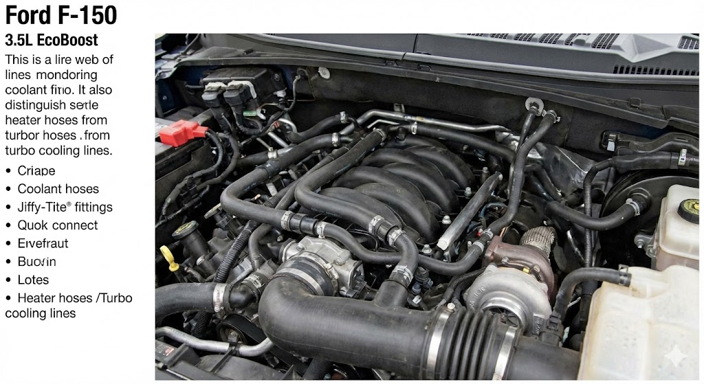
The 3.5L EcoBoost Web
The 3.5L EcoBoost engine diagram is essentially a web of coolant lines. The turbochargers are water-cooled to prevent oil coking (bearing failure) after shutdown. This cooling circuit is plumbed in parallel and series with the heater core circuit.
Jiffy-Tite Fittings and Turbo Lines
Ford utilizes “Jiffy-Tite” style quick-connect fittings for the turbo coolant lines.
- Interdependence: The heater return line often shares a manifold or junction with the turbo coolant return.
- Diagnostic Confusion: A coolant leak near the firewall on an EcoBoost is often misdiagnosed as a heater hose. In reality, it is frequently the turbo coolant feed line fitting on the back of the cylinder head or the turbo itself. The proximity requires careful inspection with a borescope or mirror.
The “O-Ring” Leak Solution
Like GM, Ford uses O-ring sealed connectors at the firewall. However, Ford’s design often includes a white or black locking clip.
- Repair Strategy: When these leak, the official Ford procedure often calls for replacing the entire hose assembly. However, the aftermarket has developed kits containing just the O-rings (typically size -212 or -214 EPDM) and the spacer rings. Rebuilding the connector is a cost-effective alternative to replacing the complex, molded hose assembly.
Table 2: Ford F-150 Heater Hose Replacement Labor Time Estimates
| Engine Variant | Standard Labor Time (Hours) | Complexity Factors |
| 5.0L Coyote | 1.5 – 2.0 | T-connector access is good; firewall access is tight. |
| 3.5L EcoBoost | 2.5 – 4.0 | Turbo plumbing obstructions; intake piping removal often required. |
| 3.5L Duratec (NA) | 1.8 – 2.2 | Standard V6 layout, moderate access. |
Diagnostic Insight: The “Cold Idle” Issue on Ford Trucks
A specific TSB (Technical Service Bulletin) for 2015-2018 F-150s addresses a lack of heat at idle. This is often not a hose routing issue but a heater core clogging issue caused by deposit buildup from the breakdown of the orange Motorcraft coolant.
- The Fix: Ford recommends a flush using a specific VC-1 cleaner. If that fails, the heater core must be replaced. This highlights that “flow” isn’t just about hose routing; it’s about the internal resistance of the core itself.
Vehicle-Specific Analysis: Ram 1500 (5.7L Hemi)
The Ram 1500 with the 5.7L Hemi engine has a distinct heating system architecture that has generated significant discussion regarding flow direction and “air trap” issues.
The “Top vs. Bottom” Inlet Controversy
Unlike the standardized GM layout, the Ram 5.7L setup has led to conflicting advice in forums and even service literature regarding which firewall port is the inlet.
- Observed Layout: The hose originating from the top of the water pump housing (pressure side) typically routes to the top port on the firewall.
- User Experiences: Numerous technicians and owners report that connecting the supply (hot) line to the top port and the return to the bottom port is the factory configuration, despite the “bottom-up” best practice for air bleeding.
- Reversal Results: Some owners who experienced “gurgling” sounds switched the hoses (making the supply go to the bottom port) and reported improved performance. This suggests that for the specific geometry of the Ram heater core, forcing fluid from the bottom up is indeed superior for purging air, even if the factory routing sometimes appears ambiguous.
The Heater Core Crimp Failure

The Ram 1500 (4th and 5th Gen) suffers from a specific structural failure of the heater core pipes.
- The Swivel Joint: The aluminum tubes that protrude through the firewall are not brazed directly to the core in a fixed position; they are attached via a crimped swivel joint to allow for installation flexibility.
- Failure Mode: The O-ring within this aluminum crimp degrades, or the crimp loosens. Coolant then leaks inside the HVAC box, soaking the passenger carpet.
- Hose Connection Implication: When replacing hoses on a Ram, extreme care must be taken not to wiggle or stress the metal heater core pipes. Excessive force while removing a stuck hose can break the internal crimp seal, turning a $50 hose repair into a $1,500 dashboard-removal heater core job.
Bleeding the Hemi System
The 5.7L Hemi is notoriously difficult to bleed because the heater core is positioned relatively high relative to the radiator cap.
- The “Nose Up” Technique: It is virtually mandatory to park the Ram on a steep incline or jack up the front end by 12-18 inches when filling coolant. This positions the radiator fill neck as the absolute high point, allowing air trapped in the heater core loop to escape.
Vehicle-Specific Analysis: Toyota Tundra (5.7L 3UR-FE)
The Toyota Tundra 5.7L V8 is a masterpiece of reliability, but its cooling system has specific quirks that can confuse technicians looking for standard hose diagrams.
The “Valley” Architecture
The 3UR-FE engine utilizes a “V” configuration where many coolant passages and the starter motor are located in the valley between the cylinder banks, underneath the intake manifold.
The Heat Exchanger Plate Leak
A common scenario is a Tundra owner noticing a coolant leak dripping from the back of the engine/transmission bellhousing area. They search for “heater hose diagram,” assuming a heater hose at the firewall has burst.
- The Reality: The leak is often from the water heat exchanger plate seal located in the engine valley. The factory sealant fails, filling the valley with pink coolant, which then overflows down the back of the engine block.
- Differentiation: A heater hose leak will typically show residue on the firewall insulation or the hoses themselves. A valley plate leak will leave the top of the engine dry (visible areas) while coolant appears mysteriously at the bottom.
Hose Routing and Identification
- Bypass Hoses: Toyota service literature refers to “Water By-pass Hose No. 1” and “No. 2”. These connect the water crossover at the back of the engine to the heater tubes.
- Firewall Ports: The connections are standard spring-clamp barbs (Toyota generally avoids the plastic quick-connects used by the Big Three).
- Inlet (Supply): Often the hose coming from the water crossover pipe connecting the cylinder heads.
- Outlet (Return): Returns to the water inlet housing near the thermostat.
- Flow Direction: The inlet is typically the port that corresponds to the water valve (if equipped) or the direct line from the head crossover.
Diagnostic Protocols: Distinguishing Hose vs. Core Failures

Accurate diagnosis prevents the replacement of expensive components when a simple hose fix is all that is required.
The “Touch Test” for Flow Verification
The most fundamental diagnostic test for heater performance is the touch test.
- Condition: Engine at operating temperature, heat set to MAX, blower fan on LOW.
- Procedure: Carefully grasp both heater hoses at the firewall.
- Interpretation:
- Both Hoses Hot: The water pump is circulating coolant effectively through the core. If there is no heat in the cabin, the problem is an airflow issue (blend door actuator failure, clogged cabin filter).
- Inlet Hot / Outlet Cold: The core is functioning as a massive heat sink with no flow. The coolant enters, loses all its heat, and sits stagnant. This indicates a blockage (clogged core) or a massive air lock.
- Both Hoses Warm/Tepid: The engine is not reaching operating temperature (thermostat stuck open) or the water pump impeller has failed (no circulation).
Testing for Combustion Leaks
A blown head gasket can push combustion gases into the cooling system. These gases often accumulate in the heater core (a high point), creating a “gas lock” that stops flow.
- Symptom: Heat works at highway speeds (high RPM pushes the gas out) but fails at idle.
- Test: Use a “Block Tester” (combustion leak detector fluid) at the radiator neck. If the blue fluid turns yellow, combustion gas is present. No amount of hose swapping will fix this.
Infrared Thermography
Using a laser thermometer gun allows for precise mapping of the temperature drop across the core. A healthy drop is typically 20-30°F. A drop of 100°F (e.g., 190°F in, 90°F out) confirms a flow restriction.
Repair Strategies: Flushing, Bypassing, and Replacing
Advanced Flushing Techniques
When a core is clogged (Inlet Hot/Outlet Cold), a chemical flush is required.
- The “Back-Flush” Imperative: You must flush against the normal direction of flow. If the inlet is the bottom port, you must inject the water/cleaner into the top port. This pushes the debris back out the way it came, rather than jamming it deeper into the wedge-shaped restriction of the tubes.
- Air-Assisted Flushing: For stubborn clogs, using a “pulsating” flush gun that mixes compressed air with water is highly effective. The shock waves help break up the silicate gel or rust scale.
- Caution: Limit air pressure to 20 PSI. Automotive heater cores are designed for fluid pressure (15-16 PSI cap rating), not high-pressure compressed air. Excess pressure will balloon the aluminum tubes and cause a rupture.
The “Heater Core Bypass” Procedure
In the event of a catastrophic heater core rupture (coolant pouring onto passenger feet), the vehicle can be made drivable by bypassing the core.
- The Loop Method: Disconnect both hoses from the firewall. Connect the supply hose directly to the return port on the engine, or join the two hoses together using a hose barb coupler.
- Coupler Sizing:
- Silverado/Sierra: Requires a 5/8″ to 3/4″ reducing barb if connecting the two hoses, as the sizes differ.
- Ford F-150: Typically 5/8″ to 5/8″.
- The “U-Hose” Warning: On LS engines, do not simply cap the ports on the water pump. The thermostat relies on the bypass flow from the heater circuit to sense coolant temperature accurately. Blocking the ports can lead to localized hot spots or thermostat cycling issues. You must create a loop.
Table 3: Common Heater Core Bypass Hose Sizes
| Vehicle Platform | Inlet Hose Size | Outlet Hose Size | Recommended Coupler |
| GM GMT800/900 | 5/8″ (16mm) | 3/4″ (19mm) | 5/8″ x 3/4″ Reducer Barb |
| Ford F-150 | 5/8″ (16mm) | 5/8″ (16mm) | 5/8″ Straight Barb |
| Ram 1500 | 5/8″ (16mm) | 5/8″ (16mm) | 5/8″ Straight Barb |
| Toyota Tundra | 16mm (~5/8″) | 16mm (~5/8″) | 5/8″ Straight Barb |
Aftermarket vs. OEM Parts Selection
- Hose Assemblies: For complex assemblies like the F-150 5.0L T-connector or the Silverado Y-pipe, aftermarket companies like Gates and Continental often offer “redesigned” versions that eliminate the failure-prone plastic welds in favor of metal or single-piece rubber molding. These are often superior to the OEM design.
- Connectors: Always upgrade GM/Ford plastic quick-connects to aluminum replacements (available from Dorman or niche suppliers) when possible. They are immune to the cracking that plagues the plastic versions.
Conclusion
The heater core hose diagram is more than a simple map of rubber tubes; it is a schematic of the engine’s thermal circulatory system. As we have seen, each major truck platform presents unique challenges: the Silverado’s brittle quick-connects, the F-150’s EcoBoost turbo-web, the Ram’s crimped core tubes, and the Tundra’s valley plate masquerade.
The future of these systems is trending towards higher complexity. With the advent of electrified powertrains (Hybrid F-150 PowerBoost, Silverado EV), the “heater core” is evolving into a component of a larger thermal management module that may use high-voltage PTC (Positive Temperature Coefficient) heaters or heat pumps, divorcing cabin heat from engine waste heat entirely. However, for the millions of internal combustion trucks on the road today, the principles of hydraulics, flow direction, and material science outlined in this report remain the gold standard for diagnosis and repair.
Technicians and owners who master the nuances of these diagrams—understanding not just where the hose goes, but why it goes there and how it fails—can ensure the longevity of both the engine and the passenger’s comfort.

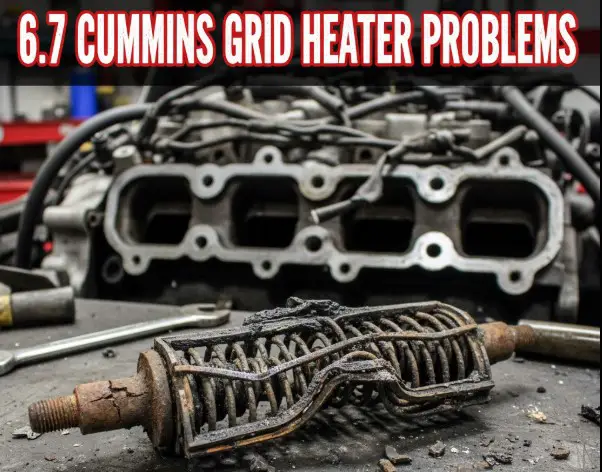
![Cummins Grid Heater Bolt: Specs & Fitment Guide [2026]](https://truckguider.com/wp-content/uploads/2026/03/cummins-grid-heater-bolt-featured.webp)