Ford F150 Front Axle Diagram: 2026 Component Breakdown

The Ford F150 front axle system utilizes an Independent Front Suspension (IFS) configuration, featuring CV half-shafts, an Integrated Wheel End (IWE) actuator, and a front differential carrier. The IWE assembly, located behind the wheel hub, relies on engine vacuum to disengage the axle, preventing unnecessary rotation of the front drivetrain components.
📌 Key Takeaways
- Torque the axle shaft nut to 20-30 lb-ft initially, then final torque to 40-50 lb-ft while rotating the wheel to ensure proper seating.
- The IWE system defaults to an engaged position if vacuum pressure drops below 5-7 inches of mercury.
- Always use high-temperature synthetic grease when servicing CV joint boots to prevent thermal breakdown.
- The most common failure point is the IWE vacuum solenoid, which can ingest water, causing grinding noises during 2WD operation.
- Seek professional service if the front differential housing shows signs of metal shavings or structural stress fractures.
Mastering the complex mechanical architecture of the Ford F150 front axle is essential for any technician tasked with maintaining or repairing modern half-ton truck drivelines. The Ford F150 front axle diagram represents a sophisticated Independent Front Suspension (IFS) layout, engineered for a balance between off-road capability and highway ride comfort. Whether you are addressing a vacuum leak in the Integrated Wheel End (IWE) system or replacing a worn-out CV axle, identifying the interaction between the differential, drive shafts, and hubs is critical. This guide utilizes industry-standard schematics to break down the assembly, power transmission paths, and the specific failure points that frequently trigger driveline noise or engagement malfunctions in 4WD systems.



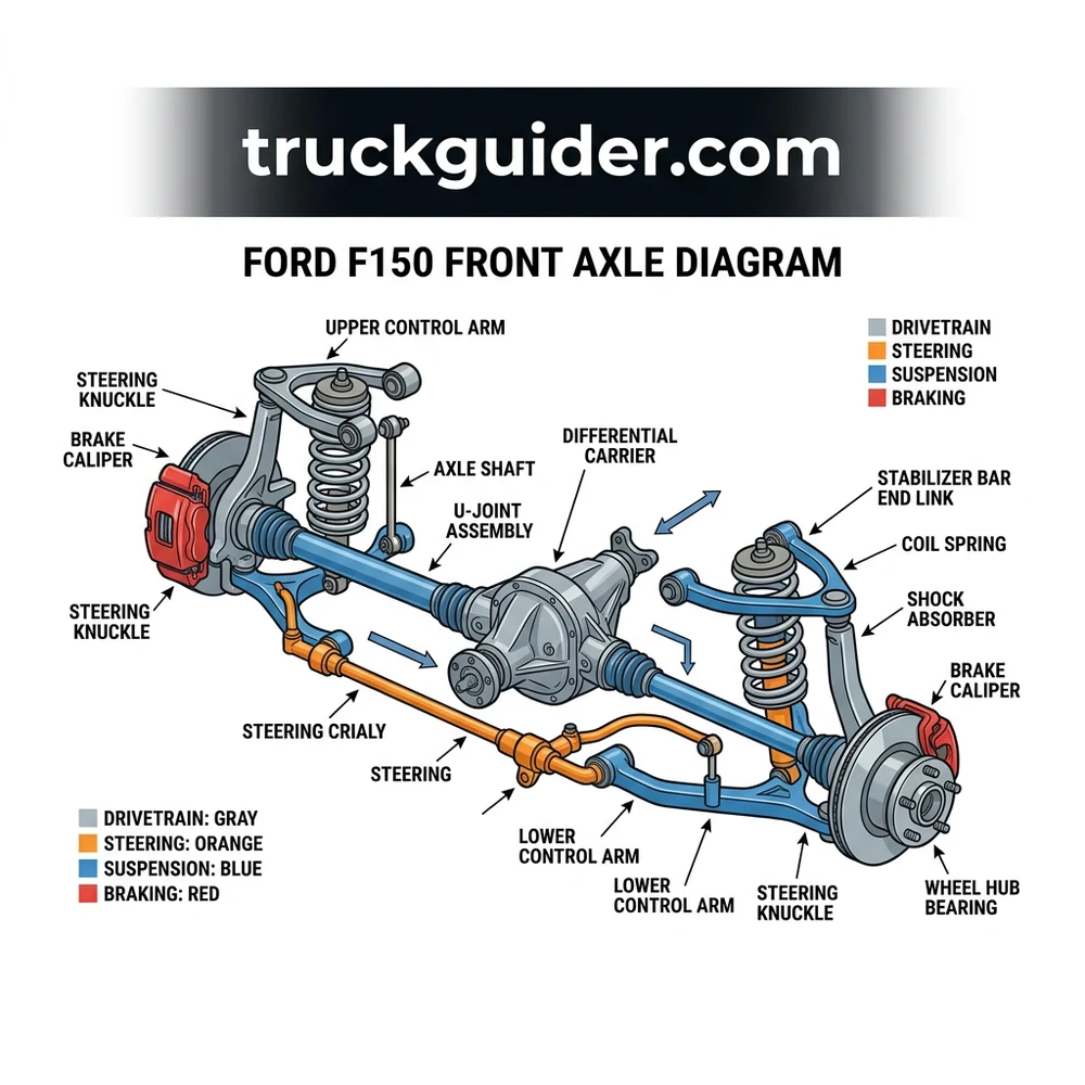
Understanding the Ford F150 Front Axle Diagram and IFS Layout

The structural configuration of the Ford F150 utilizes an Independent Front Suspension (IFS) system, a major departure from traditional solid front axles found in heavy-duty commercial equipment. In this layout, the front wheels move independently, supported by coil-over shocks and upper and lower control arms. The core of this system, as visualized in the Ford F150 front axle diagram, is the front differential carrier, which is mounted directly to the chassis crossmember. Unlike a solid axle, the differential remains stationary relative to the frame, while the axle shafts accommodate the vertical travel of the wheels through the use of constant velocity (CV) joints.
The power transmission chain begins at the transfer case, which sends torque forward through the front drive shaft (propeller shaft) to the input pinion of the front differential. Inside the differential, the ring and pinion gear set redirects the rotational force 90 degrees to the left and right axle shafts. The structure consists of the cast aluminum or iron differential housing, which contains the carrier bearings and side gears. Because the system is “independent,” the axle shafts must be articulated. This is achieved via inner tripod joints and outer Rzeppa joints encased in protective rubber boots. If your diagnostics reveal gear oil leakage, check the pinion seal or the side gear output seals first, as these are the most common leak points in this configuration.
Furthermore, the integration of the front differential into the IFS requires precise geometry. Alignment specs for caster, camber, and toe are directly influenced by the condition of the lower control arm bushings and the integrity of the axle housing mounts. If you notice excessive vibration, inspect the front drive shaft U-joints or the slip yoke spline for play. A failure in the support bushings of the differential carrier can lead to a misalignment that accelerates pinion gear wear, eventually causing a noticeable whine or growl under acceleration. Understanding this structural interplay is the first step toward effective component replacement.
Ford F150 Front Axle Diagram: CV Axles and IWE Actuation
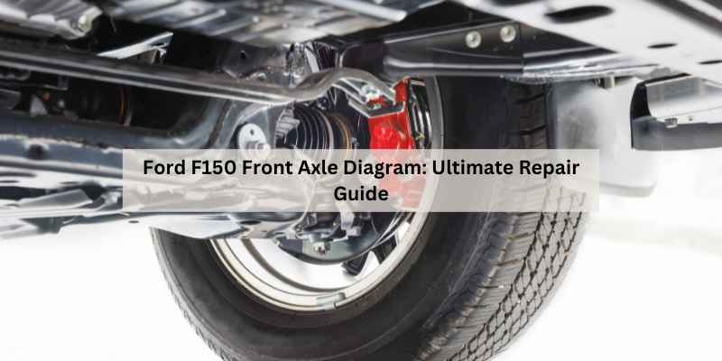
The power delivery from the differential to the wheels is governed by the CV axle shafts and the IWE system. In the Ford F150 front axle diagram, the IWE actuator is a vacuum-operated hub lock that engages the wheel to the axle shaft when 4WD is requested. When the system is in 2WD mode, vacuum pressure pulls the IWE diaphragm outward, disengaging the splined actuator from the wheel hub. This allows the wheels to rotate without turning the front axle shafts, which increases fuel efficiency and reduces wear on the front driveline components.
| Component | Primary Function | Failure Symptom |
|---|---|---|
| CV Axle Shaft | Transmits torque to hubs | Clicking at full lock |
| IWE Actuator | Vacuum-locking wheel hub | Grinding noise in 2WD |
| Hub Spline | Mechanical interface | Stripped teeth/No 4WD |
When troubleshooting the IWE, you must verify the vacuum integrity using a hand-held vacuum pump. According to OEM specifications, the system should hold at least 10–15 inches of mercury to remain fully disengaged. A common failure occurs when the IWE solenoid leaks or the rubber vacuum lines crack, resulting in partial engagement of the IWE gears. This leads to a distinct “grinding” or “marbles-in-a-can” sound while driving at highway speeds. Always check the vacuum check valve located near the vacuum reservoir; if it sticks, the IWEs may struggle to disengage even if the pump is functioning correctly.
The half-shafts are keyed to the IWE through a spline interface. When replacing these components, ensure that the splines are clean and free of debris. Applying a light coating of high-temperature wheel bearing grease to the splines during reassembly is recommended by many service manuals to prevent corrosion-induced seizing. If you are replacing the CV axle, observe the position of the C-clip on the inner stub shaft. Failure to seat this clip properly into the differential side gear will result in the axle “walking” out of the housing, potentially destroying the seal and contaminating the gear oil.
Troubleshooting Ford F150 Front Axle Diagram Component Failure
Diagnostic efforts for the F150 front end should follow a systematic process, moving from the most accessible components to the internal mechanical parts. Start by identifying the nature of the noise: clicking, grinding, or howling. A rhythmic clicking that increases in frequency with vehicle speed is a hallmark of a failing outer CV joint. Conversely, a constant howling that changes pitch with torque load points toward the differential carrier bearings or ring and pinion teeth.

Wheel Hub Bearing: Perform a lateral shake test while the vehicle is on a lift. If you detect play at the 12 and 6 o’clock positions, the unitized wheel bearing is likely compromised, which can misalign the IWE and cause intermittent engagement issues.
Suspension Control Arms: Inspect the ball joints for excessive movement. A worn lower ball joint can cause “camber roll,” putting undue stress on the CV axle joints.
Gear Oil Analysis: If you suspect internal differential wear, drain a sample of the gear oil. The presence of metallic flakes or a burnt odor suggests catastrophic failure of the limited-slip clutch packs or the side gears.
Vacuum System: If the 4WD system fails to engage, use a vacuum gauge at the IWE actuator fitting. If no vacuum is present, trace the line back to the solenoid.
* Spline Wear: Inspect the IWE engagement teeth for rounding. If they are worn, they will fail to mesh with the hub, causing the teeth to “ratchet” against each other.
Never attempt to force the IWE into engagement if you suspect a vacuum leak. Driving with a partially engaged actuator will cause rapid destruction of the wheel hub teeth and can force debris into the wheel speed sensor, triggering an ABS fault light.
How to Service Your Ford F150 Front Axle Assembly
Servicing the front axle assembly requires specific tooling, including a spindle puller, a torque wrench capable of reaching 200+ lb-ft for the axle nut, and a vacuum pump for system validation. Before beginning, ensure the vehicle is secured on jack stands at the frame, allowing the suspension to hang freely. Begin by removing the wheel, brake caliper, and rotor. Once the spindle nut is removed, use a rubber mallet to free the CV axle from the hub spline.
1. Drain the differential: Locate the drain plug on the bottom of the differential housing. Use a 3/8-inch square drive to remove it. Inspect the magnetic tip for excessive fine iron filings.
2. Remove the half-shafts: If you are pulling the axles, you must disconnect the sway bar link and the lower ball joint to gain enough clearance for the CV joint to clear the differential housing.
3. Seal Replacement: If you are replacing the pinion seal or output seals, use a seal driver of the appropriate diameter to avoid cocking the new seal in the bore.
4. Component Inspection: Check the CV boots for tears. If a boot is torn, grease will be slung out, and road debris will destroy the joint bearings within a few hundred miles.
5. Reinstallation: Torque the axle nut to the factory specification—typically between 180–200 lb-ft, depending on the model year. Use only a new nut, as these are often designed as “torque-to-yield” or single-use locking fasteners.
6. Final Vacuum Test: Once reassembled, reconnect the IWE vacuum lines and perform a static engagement test to ensure the hubs lock and unlock correctly.
Standard gear oil for the front differential is SAE 75W-85 or 75W-90 synthetic, depending on your axle code. Always confirm the capacity using your owner’s manual, as modern aluminum housings are sensitive to overfilling, which can lead to seal blowout.
Ford F150 Front Axle Diagram Questions Answered
Does the Ford F150 front axle require regular maintenance?
While the front differential uses “lifetime” synthetic fluid, industry best practices suggest changing the gear oil every 60,000 to 100,000 miles, especially in heavy-duty or off-road environments. Regular inspections of the CV boots and IWE vacuum lines can prevent more costly repairs down the line.
Why does my truck grind only in 2WD mode?
This is almost exclusively an IWE system issue. If the IWE actuator does not receive enough vacuum to fully disengage, the teeth will graze the hub. This creates a grinding noise that typically stops when you switch into 4WD (which cuts the vacuum and forces the IWE into full engagement).
Can I upgrade the IWE system to manual hubs?
Yes, several aftermarket manufacturers offer “IWE Eliminator” kits. These kits replace the vacuum-actuated gear with a permanently engaged hub. While this increases reliability by removing the vacuum requirement, it means your front axle shafts will spin constantly, which may result in a negligible decrease in fuel economy and slightly increased wear on the front CV joints over time.
What torque spec should be applied to the axle nut?
Torque specs for the front axle nut vary by generation. For most 2015–2020 models, the specification is approximately 200 lb-ft. Always consult your specific service manual based on your VIN to avoid overtightening, which can preload the wheel bearings and lead to premature failure.
Are the left and right CV axles interchangeable?
In most F150 configurations, the left and right CV axles are not identical due to the different lengths required to reach the differential housing. Always verify the part number for the specific side you are replacing. Mixing up these components can cause binding during suspension articulation.
Step-by-Step Guide to Understanding the Ford F150 Front Axle Diagram
Identify – Locate the CV axle shaft and the corresponding vacuum lines on the rear of the steering knuckle.
Locate – Find the vacuum solenoid mounted near the battery tray or firewall, depending on your specific F150 configuration.
Reference – Cross-reference the diagram callouts with your physical components to ensure proper orientation of the half-shaft splines.
Connect/Route – Route new vacuum lines according to the diagram, ensuring no kinks occur near the suspension mounting points.
Verify – Apply vacuum with a hand pump to the IWE to ensure the actuator disengages the hub as shown in the layout.
Troubleshoot – If grinding persists, refer back to the diagram to check for vacuum leaks at the check valve or solenoid connections.