Lightning Bolt on Dash: The Definitive Guide to Ram, Dodge & Jeep Electronic Throttle Control (ETC) Failures, Diagnostics, and Repairs
The automotive industry’s transition from mechanical linkage to digital control systems represents one of the most significant evolutions in modern vehicle engineering. For nearly a century, the driver’s intent was communicated to the engine via a direct physical connection—a braided steel cable linking the accelerator pedal to the throttle butterfly valve.
This mechanical simplicity offered reliability but lacked the precision required for increasingly stringent emissions regulations and the integration of advanced safety systems.
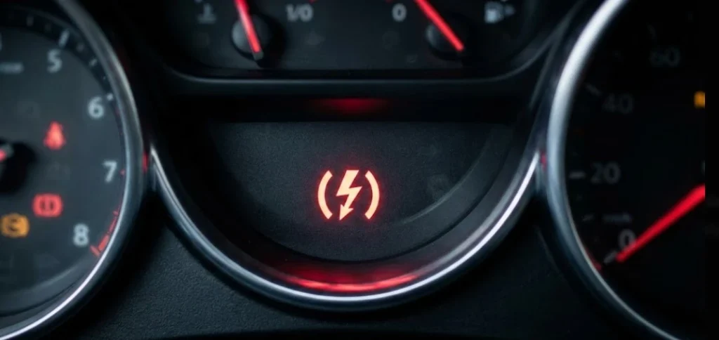
The introduction of Electronic Throttle Control (ETC), colloquially known as “drive-by-wire,” severed this physical link. In vehicles manufactured by the former Chrysler Group (now under Stellantis)—including Ram, Dodge, Jeep, and Chrysler models—this system introduced a new diagnostic paradigm. The dashboard indicator for this system, a red lightning bolt symbol enclosed in reversed parentheses )⚡(, has become a source of significant anxiety for owners.
Unlike the amber Check Engine Light (MIL), which typically denotes emissions-related inefficiencies allowing for continued operation, the red lightning bolt signifies a critical fault in the primary interface between the driver and the powertrain.
When this indicator illuminates, the Engine Control Module (ECM) has detected a loss of correlation between the requested torque (pedal position) and the delivered air intake (throttle blade angle). To mitigate the risk of unintended acceleration, the system defaults to a fail-safe state known as “Limp Mode.”
This report provides an exhaustive analysis of the ETC system’s architecture, failure vectors specific to the 5.7L HEMI and 6.7L Cummins platforms, and the diagnostic protocols necessary to resolve these complex electromechanical faults.
The Semiotics of the Lightning Bolt
The choice of a lightning bolt icon is deliberate. It serves to distinguish electrical actuation faults from mechanical or combustion anomalies. While the check engine light warns of long-term health or emissions compliance issues, the lightning bolt acts as an immediate operational alert. It signals that the computer is no longer confident in its ability to modulate the engine’s air supply safely.
This distinction is critical: a flashing lightning bolt requires immediate cessation of driving, whereas a solid light may permit a “limp home” scenario under restricted performance.
The Red Lightning Bolt
Decoding the Electronic Throttle Control (ETC) Warning Light
Detailed Data & Diagnostic Guide for Truck Owners
What Just Happened?
If you see a red lightning bolt symbol (often roughly between parentheses) on your dashboard, your vehicle’s Electronic Throttle Control (ETC) system has detected a fault.
Unlike older vehicles with a physical cable connecting your foot to the engine, modern trucks use “Drive-by-Wire.” This light means the computer has lost confidence in the signal between your gas pedal and the engine’s throttle body.
⚠️ Immediate Safety Warning
Your vehicle may enter “Limp Mode” drastically reducing speed to protect the engine.
Drive-by-Wire
No physical cable. All electronic signals.
Limp Mode
Speed capped at ~30 MPH for safety.
Why Is It On?
We analyzed repair reports from major truck forums (F-150, Ram, Silverado). The ETC system is complex, but the failure points are predictable.
The Throttle Body is the most common culprit. Carbon buildup jams the internal flap, confusing the sensors.
- Dirty/Bad Throttle Body (Most Likely)
- Pedal Position Sensor (Wear & Tear)
- Wiring or Connectors (Corrosion)
Source: Aggregated Mechanics Data & Forum Reports
The Symptom Matrix
Not all Lightning Bolts act the same. The severity depends on which component has failed. A dirty throttle body might just cause a rough idle, while a sensor failure triggers full Limp Mode.
Rough Idle / Stalling
The engine RPM fluctuates wildly at stoplights. Often caused by carbon buildup jamming the butterfly valve.
Non-Responsive Pedal
You press the gas, but the RPMs don’t move. The ECU has cut throttle input to prevent runaways.
How to Diagnose & Fix It
Don’t throw parts at the problem. Follow this logical path to save money.
Restart The Engine
Sometimes it’s just a voltage glitch. Turn off, wait 1 minute, restart.
Check For Codes (OBDII)
Look for P2135, P2119, or P2121.
Inspect Throttle Body
Remove intake hose. Look for black carbon sludge (gunk) around the flap.
Check Pedal Sensor
Check wiring at the gas pedal. If wiring is good, the sensor is likely dead.
The Cost of Repair
Should you do it yourself? The “Lightning Bolt” repairs are often surprisingly DIY-friendly. The Throttle Body is right on top of the engine, and the Gas Pedal is just 3 bolts.
💡 DIY Tip
Cleaning a Throttle Body costs $10 for a can of cleaner. A mechanic may charge $300 to replace it immediately.
Prevent Future Failures
Clean Regularly
Clean throttle body every 50k miles.
Check Battery
Low voltage can trigger false ETC codes.
Inspect Wiring
Check connectors for corrosion annually.
© 2026 TruckGuider Infographics
System Architecture and Operational Logic
To diagnose failures within the ETC system, one must first understand the complex interplay of its components. The system operates as a closed-loop feedback mechanism, continuously verifying that the mechanical reality matches the digital command.
The Accelerator Pedal Position Sensor (APPS)
The driver’s input is captured by the Accelerator Pedal Position Sensor (APPS). Unlike a simple on/off switch, the APPS is a precision instrument containing two independent potentiometers (variable resistors) or Hall-effect sensors.
- Redundancy: The two sensors, typically labeled APPS 1 and APPS 2, provide redundant signals to the ECM. As the pedal is depressed, APPS 1 might increase voltage from 0.5V to 4.5V, while APPS 2 might ramp from 0.25V to 2.25V.
- Correlation Logic: The ECM continuously compares these two signals. They must track each other within a strict tolerance window. If the signals diverge—for example, if APPS 1 indicates 50% throttle while APPS 2 indicates 10%—the ECM identifies a correlation fault (P2138) and triggers the lightning bolt.
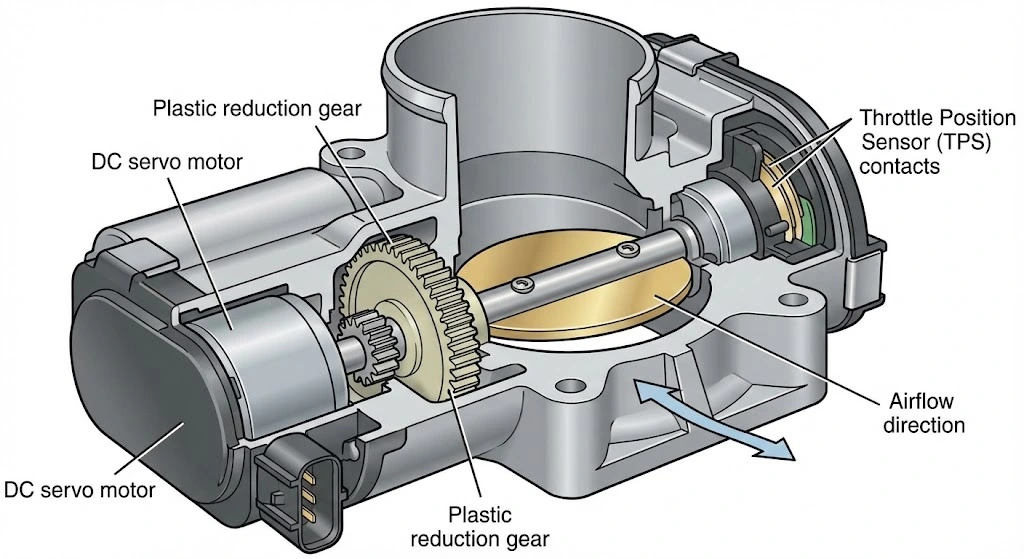
The Electronic Throttle Body (ETB)
The execution of the driver’s command occurs at the Electronic Throttle Body.
- DC Servo Motor: A high-speed electric motor drives the butterfly valve via a reduction gearset (often utilizing plastic gears in OEM units). This motor must be capable of rapid adjustments to smooth out idle or respond to sudden torque demands.
- Throttle Position Sensor (TPS): Integrated into the side of the throttle body is the TPS. Like the APPS, it often uses dual signal paths to report the exact angle of the butterfly plate back to the ECM. This feedback loop allows the computer to confirm that the motor actually moved the plate to the commanded position.
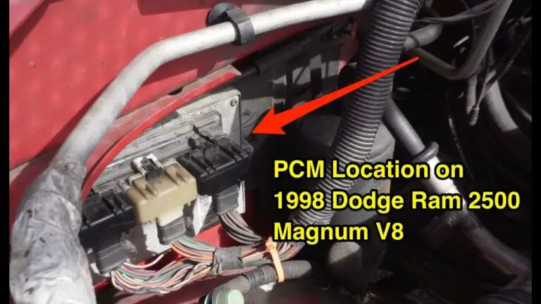
The Engine Control Module (ECM/PCM)
The brain of the system, the ECM, processes inputs from the APPS, TPS, Mass Air Flow (MAF), Manifold Absolute Pressure (MAP), and engine RPM sensors. It calculates the required throttle opening not just based on the pedal, but also factoring in:
- Idle Control: Maintaining engine speed when the compressor engages or steering loads increase.
- Traction Control: Closing the throttle to reduce torque when wheel slip is detected.
- Cruise Control: Maintaining speed without pedal input. The lightning bolt warning is triggered when the ECM’s complex algorithm detects a “Rationality Fault”—a situation where the physics of the engine (airflow, RPM) do not match the reported positions of the throttle or pedal.
Visualizing the Data Flow
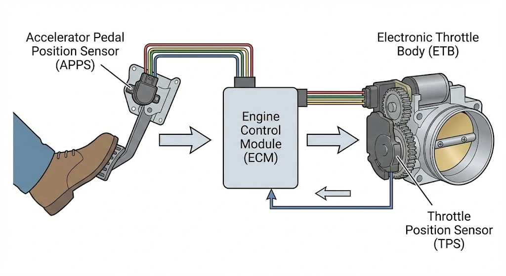
- Input: Driver presses pedal -> APPS sends dual voltage signals to ECM.
- Processing: ECM validates APPS signals -> Calculates desired torque -> Sends Pulse Width Modulated (PWM) current to ETB Motor.
- Actuation: ETB Motor spins gears -> Butterfly valve opens.
- Feedback: TPS senses valve angle -> Sends dual voltage signals back to ECM.
- Verification: ECM compares TPS signal to commanded angle. If matched, operation continues. If mismatched > Red Lightning Bolt.
Failure Modes: The Lightning Bolt Warning
The manifestation of the warning light varies depending on the severity of the fault. Understanding these variations is the first step in triage.
Solid vs. Flashing Warning
- Solid Red Lightning Bolt: This indicates a “Soft Fault” or a stored historic fault that is currently active but managed. The system has detected an anomaly—such as a slow response from the throttle body or a slight voltage drift in the pedal sensor—but can still maintain reasonable control. The vehicle will likely feel sluggish, as the ECM dampens throttle response to prevent sudden surges.
- Flashing Red Lightning Bolt: This indicates a “Hard Fault” or critical failure. The ECM has determined that throttle control is compromised to a dangerous degree. In this state, the ECM typically cuts power to the throttle motor completely. The butterfly valve is forced by an internal spring to a “default” position (usually 6-7% open). This allows the engine to idle and perhaps creep forward, but the accelerator pedal will be totally unresponsive. This is a severe safety lockout.
Limp Mode Dynamics
“Limp Mode” is a generic term, but in the context of ETC failure, it involves specific operational restrictions designed to protect the powertrain and occupants.
- RPM Limitation: The engine is often governed to a maximum of 2,000–3,000 RPM.
- Forced Idle: In severe cases, the engine will act normally at idle but refuse to rev when the pedal is pressed (The “Dead Pedal”).
- Transmission Lock: The transmission may refuse to shift into overdrive or may lock itself in a low gear (2nd or 3rd) to limit vehicle speed while allowing high-RPM limp capability to get off a highway.
The “Christmas Tree” Effect
The ETC system does not live in a vacuum. It shares data with the Anti-Lock Braking System (ABS) and Electronic Stability Program (ESP).
- ESP/BAS Lights: Because the Stability Program relies on throttle modulation to control vehicle slides, a fault in the throttle system automatically disables the ESP. Consequently, the traction control light (skidding car icon) almost always illuminates alongside the lightning bolt.
- Check Engine Light: The regulatory framework requires an emissions-related code to be set if throttle control affects combustion efficiency. Thus, a P-code is stored, and the MIL illuminates.
Diagnostics: Deciphering the Trouble Codes
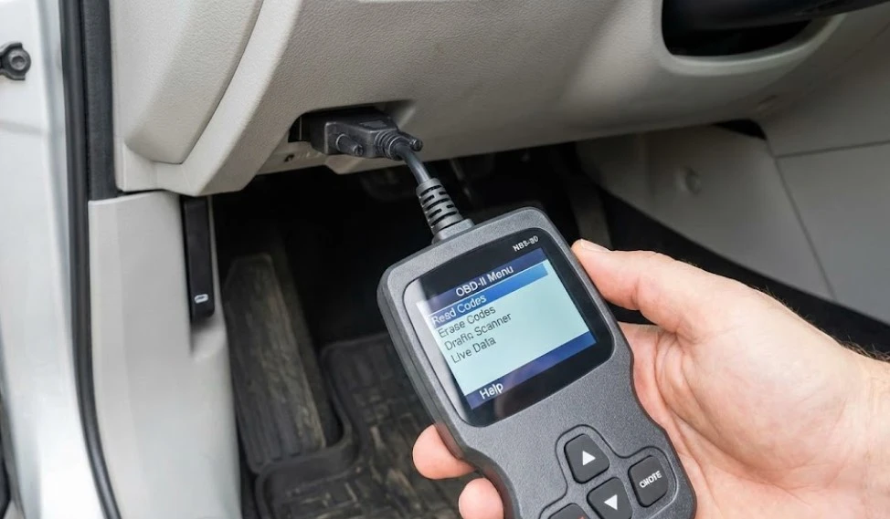
Effective repair begins with accurate diagnosis via the On-Board Diagnostics (OBD-II) port. The lightning bolt is the symptom; the Diagnostic Trouble Code (DTC) is the roadmap.
Critical ETC Diagnostic Trouble Codes
| Code | Definition | Technical Implications | Likely Component | Severity |
| P0121 | Throttle/Pedal Position Sensor A Circuit Range/Performance | The signal from the TPS is fluctuating rapidly or falling out of the expected range during operation. | Throttle Body | Medium |
| P0652 | Sensor Reference Voltage B Circuit Low | The 5-volt reference signal supplying the sensors has shorted to ground. This affects multiple sensors (MAP, AC Pressure, Oil Pressure). | Wiring Harness | High |
| P2110 | Throttle Actuator Control System – Forced Limited RPM | The ECM has intentionally limited engine speed to protect the system. This is a “consequence” code, not a “cause” code. | ECM Logic | High |
| P2118 | Throttle Actuator Control Motor Current Range/Performance | The current draw (Amperage) of the throttle motor is out of spec. Too high = Stuck plate. Too low = Broken internal circuit/fuse. | Throttle Body / Fuse | High |
| P2121 | Accelerator Pedal Position Sensor 1 Performance | Sensor 1 in the pedal assembly is providing erratic data or has a “dead spot” in its sweep. | Accelerator Pedal | Medium |
| P2135 | Throttle/Pedal Position Sensor A/B Voltage Correlation | The voltage signals from TPS 1 and TPS 2 inside the throttle body do not match the expected correlation map. | Throttle Body | High |
| P2138 | Accelerator Pedal Position Sensor D/E Voltage Correlation | The voltage signals from APPS 1 and APPS 2 inside the pedal assembly do not match. | Accelerator Pedal | High |
| P2172 | Throttle Actuator Control System – Sudden High Airflow Detected | The throttle plate moved open unexpectedly, or a massive vacuum leak occurred, causing airflow to exceed the commanded amount. | Vacuum Leak / TB | High |
| P2262 | Turbo Boost Pressure Not Detected | Specific to Diesel engines. Often triggered alongside ETC codes due to MAP sensor fouling or turbo actuator issues. | Turbo / MAP | Medium |
Voltage Drop and Multimeter Testing
While a scan tool is essential, a multimeter can isolate component failures from wiring issues.
- Testing the APPS: With the key ON and engine OFF, back-probe the signal wire at the pedal connector. A healthy potentiometer should show a smooth, linear rise in voltage as the pedal is depressed. Any sudden drop to 0V or spike indicates a physical wear spot on the sensor track—a common failure on high-mileage trucks.
- The Wiggle Test: With the engine idling, gently wiggle the wiring harness at the throttle body connector and the main harness near the oil filter. If the engine stumbles or the lightning bolt flashes, the fault is intermittent wiring contact (fretting or chaffing) rather than a failed component.
Component Deep Dive: The Electronic Throttle Body (ETB)
The ETB is the single most common failure point in gasoline applications (5.7L Hemi, 3.6L Pentastar). Its failure is rarely electronic in origin; rather, it is a mechanical failure induced by environmental factors.
The Carbon Coking Mechanism
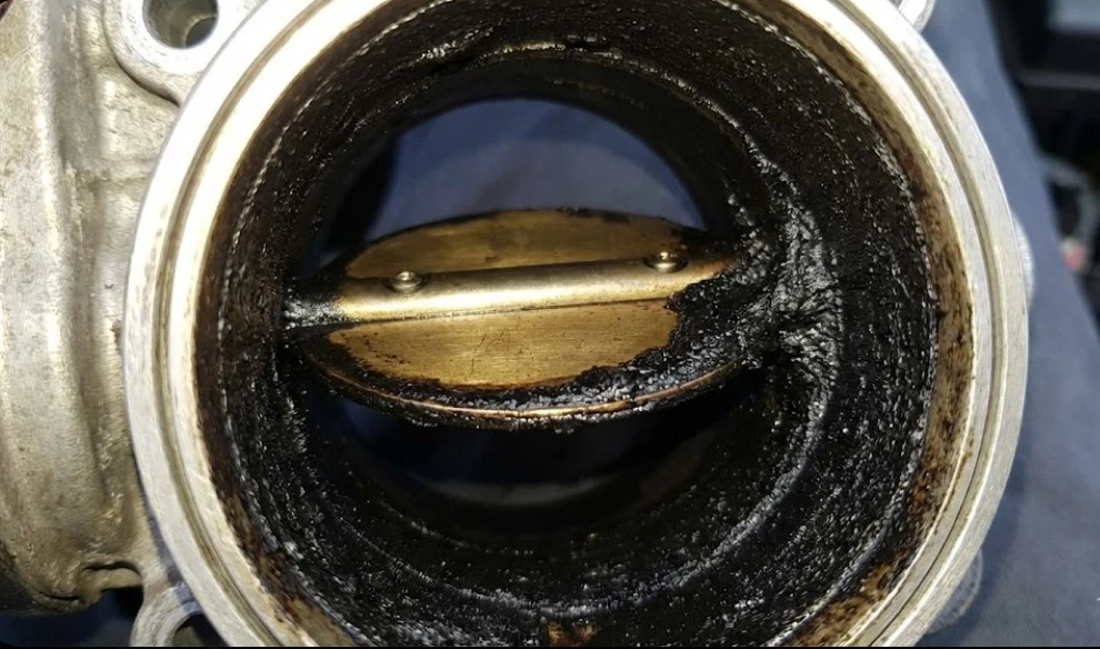
The root cause of most ETB failures is the Positive Crankcase Ventilation (PCV) system. To reduce emissions, oil vapors and blow-by gases from the crankcase are vented into the intake manifold to be burned.
- Deposition: These hot vapors pass directly over the throttle body blade. As the blade is cooler than the vapor, the oil condenses, mixing with airborne dust to form a sticky black sludge known as “coke.”
- Mechanical Binding: In cold weather, this sludge hardens. When the driver presses the gas, the electric motor attempts to push the blade open but encounters resistance from the hardened sludge.
- The Fault Trigger: The ECM detects that the motor is drawing excessive current (Amps) to move the blade (Code P2118) or that the blade is moving slower than commanded (Code P0121). It interprets this as a component failure and triggers the lightning bolt.
Internal Gear Fatigue
The reduction gears transferring force from the servo motor to the blade shaft are typically manufactured from reinforced nylon or plastic composites to reduce weight and noise.
- Wear Pattern: Over 150,000+ miles (or 200,000+ km), the teeth on these gears wear down, particularly in the “cruise” range (slight opening) where the throttle sits for 90% of driving.
- Skipping: Eventually, the gears may skip a tooth or bind, causing a permanent misalignment between the motor and the blade. This triggers a correlation code (P2135) that cannot be fixed by cleaning; the unit must be replaced.
Preventative Maintenance: The Oil Catch Can
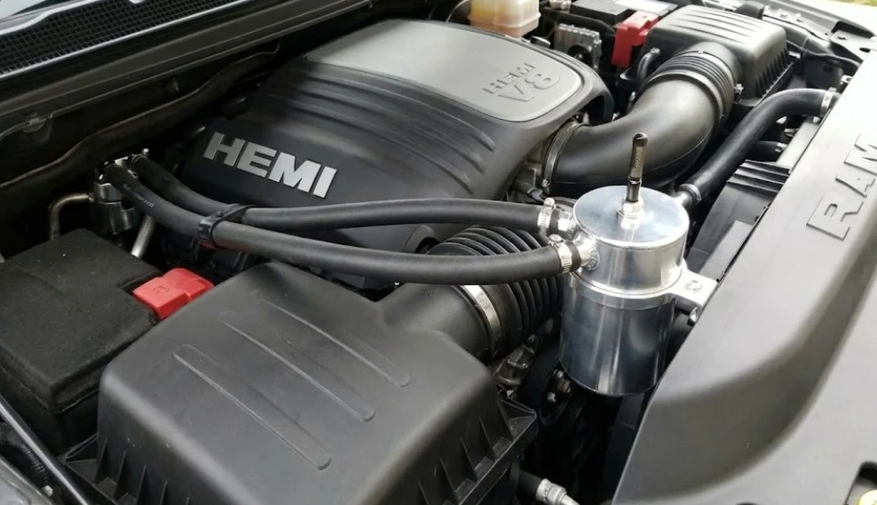
For owners of the 5.7L Hemi, installing an oil catch can is a widely recommended modification. The catch can sits in-line on the PCV hose, condensing the oil vapors into a reservoir before they reach the intake. This dramatically reduces carbon buildup on the throttle body, preventing the “coking” failure mode entirely.
Engine Specific Analysis: 5.7L HEMI V8
The 5.7L Hemi, a staple of the Ram 1500 and Dodge Charger/Challenger lineup, exhibits specific behaviors regarding the lightning bolt.
The Wiring Harness Chafing Issue
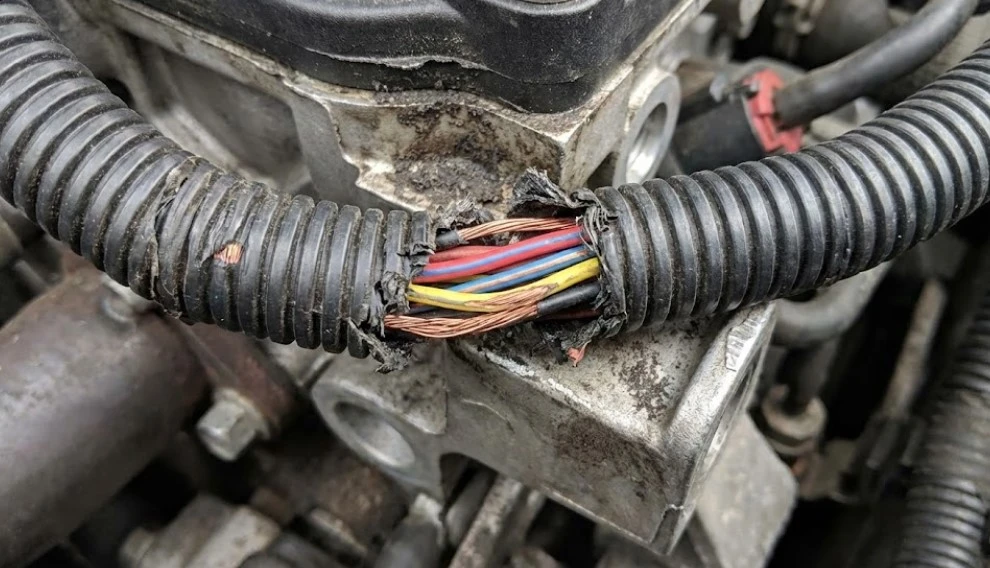
A documented manufacturing defect affects 2004–2012 and some 4th Gen (2013-2018) Ram trucks. The main engine wiring harness is routed in close proximity to the accessory drive bracket (near the AC compressor) and the oil filter housing.
- The Failure: Engine vibration causes the protective loom to wear through, eventually exposing the copper wire insulation.
- The Short: The wire carrying the 5-volt reference signal or the throttle signal shorts against the metal engine block. This causes intermittent, seemingly random lightning bolt warnings that disappear when the engine shifts on its mounts (e.g., turning corners or accelerating).
- Visual Inspection: Owners must inspect the harness near the oil dipstick tube bracket and the AC compressor. Look for signs of abrasion on the tape or exposed copper. Repair involves splicing in new wire sections and adding robust loom protection.
Temperature Sensitivity
Hemi owners frequently report the lightning bolt appearing only on very cold mornings (below freezing). This is often a combination of:
- Battery Voltage: A weak battery drops voltage significantly during cold cranking. If the system voltage drops below ~10V, the ECM may fail to initialize the throttle sensors correctly, triggering a “ghost” code.
- Ice/Sludge: Moisture in the PCV sludge freezes, physically locking the throttle blade until engine heat melts it.
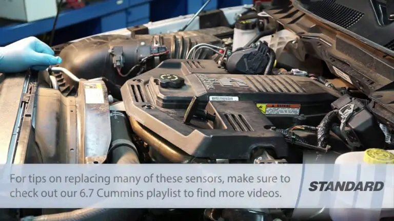
Engine Specific Analysis: 6.7L Cummins Diesel
The ETC warning on the 6.7L Cummins platform (Ram 2500/3500/4500/5500) carries significantly higher stakes. While it can indicate a simple sensor fault, it is also the primary warning sign for a catastrophic engine-killing design flaw.
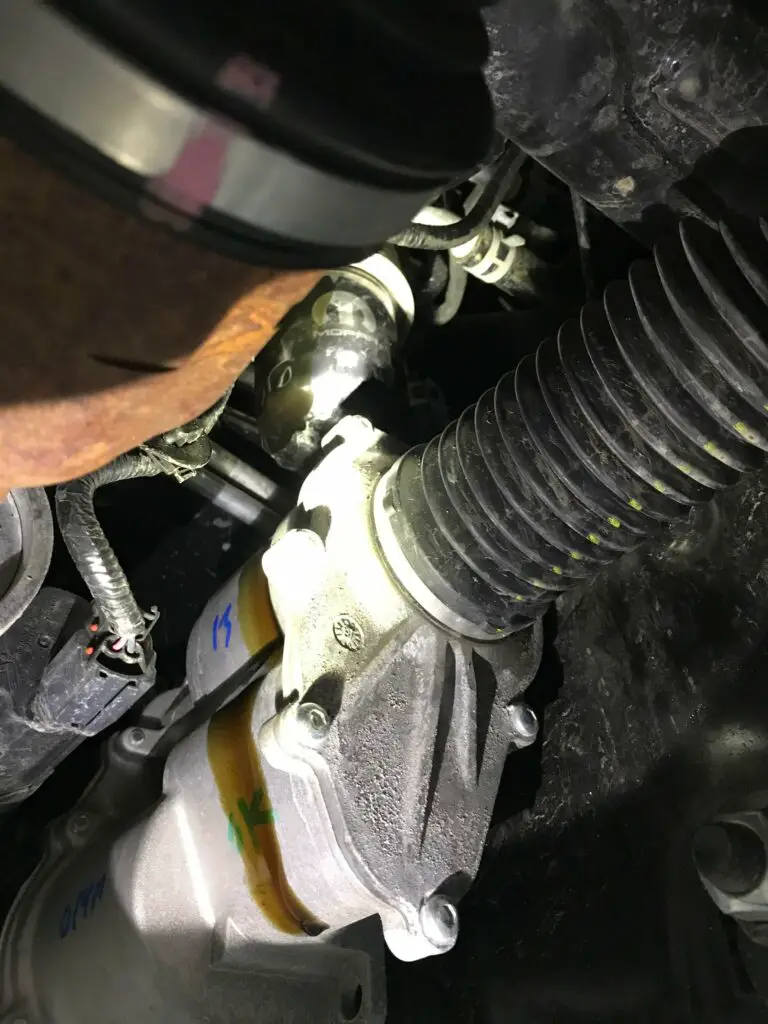
The “Killer” Grid Heater Bolt

The 6.7L Cummins uses an intake air heater grid (a toaster-like element) to warm the air for cold starts, replacing glow plugs. This grid is connected to the battery via a stud and nut assembly on the bottom of the intake horn.
- The Flaw: The nut securing the power cable is prone to loosening due to diesel vibration and thermal cycling. Furthermore, high current draw can cause arcing, melting the stud.
- The Catastrophe: If the bolt/nut falls off, it drops directly into the intake runner and is sucked into Cylinder #6. The piston slams the bolt into the valves and cylinder head, instantly destroying the engine.
- The Warning: Often, before the bolt falls, the loose connection causes resistance fluctuations in the circuit. The ECM monitors the voltage drop across the grid heater. An irregular voltage signature (Code P2609) or associated electrical noise can disrupt the 5-volt reference shared with the ETC system, triggering the lightning bolt warning.
- Action: ANY lightning bolt warning on a 6.7L Cummins should trigger an immediate inspection of the intake grid heater stud. If it shows signs of wobbling or arcing, the truck should not be driven until the grid heater is replaced or deleted.
MAP Sensor Sooting and Turbo Actuators
The Variable Geometry Turbocharger (VGT) on the Cummins relies on the Manifold Absolute Pressure (MAP) sensor to manage boost.
- Soot Buildup: The Exhaust Gas Recirculation (EGR) system introduces soot into the intake. This soot coats the MAP sensor, insulating it and clogging its port.
- The Correlation: When the MAP sensor sends sluggish or stuck data, the ECM cannot reconcile the boost pressure with the throttle valve position and engine load. This “rationality fault” triggers the lightning bolt and often Code P2262 (Turbo Boost Pressure Not Detected).
- Remedy: The MAP sensor (located on the intake manifold) should be removed and cleaned with MAF sensor cleaner or replaced as part of regular maintenance (every 50k miles) on EGR-equipped trucks.
Diagnostic Strategy: A Step-by-Step Flowchart
When the lightning bolt strikes, follow this logical progression to avoid unnecessary part replacement.
Phase 1: The Field Reset (Soft Fix)
If the light appears while driving but the vehicle is drivable:
- Pull Over: Safely stop the vehicle and turn off the engine.
- Wait: Allow 60 seconds for the ECM to power down and write to memory.
- Restart: Start the engine. If the light is gone, it was likely a transient “soft code” caused by a voltage spike or momentary glitch.
- Monitor: If it returns, proceed to Phase 2.
Phase 2: Code Retrieval and Analysis
Using an OBD-II scanner is non-negotiable.
- Scan: Record all P-codes.
- Categorize:
- Throttle Body Codes: P2110, P2118, P0121, P2135.
- Pedal Codes: P2121, P2122, P2123, P2138.
- System Codes: P0652 (Voltage Low), U-codes (Communication loss).
- Note: If you see P2110 (Forced Limited RPM), ignore it initially. It is a symptom of the car entering limp mode, not the cause.
Phase 3: The “Throttle Relearn” Procedure
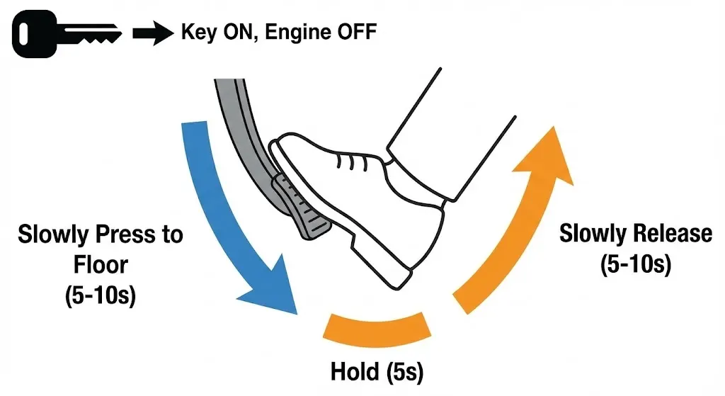
Before buying parts, attempt to recalibrate the system. This synchronizes the APPS and TPS values in the ECM.
- Insert Key, turn to ON/RUN position. DO NOT START ENGINE.
- Wait for the dashboard lights to stabilize (Check Engine light stops flashing).
- Slowly and deliberately press the accelerator pedal to the floor (take 5-10 seconds).
- Hold at the floor for 5 seconds.
- Slowly release the pedal to the top position (take 5-10 seconds).
- Turn Key to OFF.
- Restart engine. Why this works: This procedure teaches the ECM the exact voltage limits (0% and 100%) of the pedal travel, correcting for any mechanical wear or drift.
Phase 4: Inspection and Cleaning (Gas Engines)
If codes point to the Throttle Body (P2118, P0121):
- Disconnect Battery: Negative terminal off. This is crucial for safety and resetting the ECM’s learned fuel trims.
- Remove Intake Tube: Expose the throttle body blade.
- Inspect: Look for the black ring of carbon sludge around the blade edge.
- Clean: Spray Throttle Body Cleaner (NOT Brake Cleaner) onto a rag or soft brush. Gently wipe the bore and blade edges. Manually push the blade open to clean the underside.
- Reassemble and Relearn: Reconnect battery and perform the relearn procedure from Phase 3.
Phase 5: Component Replacement
If cleaning fails or correlation codes (P2135, P2138) persist, replace the faulty unit.
- Throttle Body: Ensure the new unit comes with a new gasket. Torque bolts to 8-10 ft-lbs (do not overtighten; the manifold is plastic).
- Accelerator Pedal: Requires removing 2-3 bolts at the firewall and one electrical connector. No calibration is needed other than the “Phase 3” relearn.
Repair Cost Analysis and Parts Selection
The financial impact of an ETC failure varies wildly based on the diagnosis.
OEM vs. Aftermarket Parts
The market is flooded with cheap sensors, but the ETC system is safety-critical.
- Throttle Bodies:
- OEM (Mopar): $300 – $500. Highest reliability. Recommended for long-term ownership.
- Tier 1 Aftermarket (Bosch, Hitachi, VDO): $150 – $250. These are often the same units as OEM, just re-boxed. Excellent value.
- Economy (White Box/Amazon): $50 – $100. High Risk. Community reports suggest a high failure rate within 6-12 months. Do not use for critical components.
- Accelerator Pedals:
- OEM: $150 – $250.
- Aftermarket: $80 – $150. Given the “dead spot” issues with cheap potentiometers, OEM or Standard Motor Products (SMP) ‘T-Series’ are recommended.
Labor Costs
- Throttle Body Replacement:
- DIY: 30-60 minutes. Difficulty: 2/10.
- Shop: 1.0 – 1.5 hours labor ($150 – $250) + Parts markup.
- Wiring Repair (Harness Chafing):
- DIY: $10 (Tape/Solder). Difficulty: 6/10 (Access is tight).
- Shop: Diagnosis time can be extensive (2-4 hours). Expect bills over $500 if the mechanic has to hunt for the short.
Frequently Asked Questions (FAQ)
Q: Can I drive my truck with the red lightning bolt on?
A: If the light is flashing, absolutely not. The throttle is disabled, and you have no control over acceleration. If the light is solid, the vehicle is likely in a protective “limp mode.” You may be able to drive a short distance at reduced speed to get to safety, but prolonged driving can damage the catalytic converters (due to rich fuel mixtures) or leave you stranded if the fault degrades to a hard failure.
Q: Why does the lightning bolt come on when I tow a heavy trailer?
A: Heavy towing places maximum load on the engine, creating high heat and vibration. This can exacerbate intermittent wiring faults (like the grid heater bolt on Diesels or harness chafing on Hemis). Additionally, if the transmission overheats or slips, the ECM may trigger a general powertrain fault that includes the ETC light to limit engine power and protect the transmission.
Q: Does a weak battery really cause this light?
A: Yes. The ETC system runs on a 5-volt reference signal derived from the main 12-volt system. If the battery is weak, voltage can dip below the threshold required for the ECM to accurately read the sensors during cranking (start-up). This sets a “ghost” code. If your battery is over 3-4 years old, load testing it is the first diagnostic step.
Q: I replaced the throttle body, but the light is still on. What now?
A: Did you perform the relearn procedure? The ECM has “learned” the behavior of the old, broken throttle body. It needs to be calibrated to the new one. Disconnect the negative battery terminal for 15 minutes to clear the adaptive memory, then perform the “Pedal Dance” (Phase 3 in Diagnostics).
Q: Is there a recall for this?
A: While there is no blanket recall for the lightning bolt itself (as it is a symptom, not a single part), there have been specific Technical Service Bulletins (TSBs) and recalls for related components. For example, recall V06 addressed a stuck throttle issue in certain Dodge vehicles, and TSB 18-024-20 addresses ETC software updates for Ram trucks. Always check your VIN with the NHTSA or a dealer.
Visual Aids and Charts
Visual Plan: Throttle Body Schematic
(Suggested Diagram Description: A cross-section of an electronic throttle body. Labels should indicate the DC Motor, the Reduction Gears, the Return Spring, the Butterfly Valve, and the TPS contacts. Arrows should show the airflow path and the location where carbon sludge accumulates—typically on the back of the butterfly valve and the bore wall.)
Data Table: 5.7L Hemi vs. 6.7L Cummins ETC Failures
| Feature | 5.7L Hemi (Gas) | 6.7L Cummins (Diesel) |
| Primary Throttle Function | Airflow Control (RPM/Torque) | EGR Mixing / Shutdown Anti-Shudder |
| Most Common ETC Cause | Carbon Buildup on Throttle Blade | Grid Heater Bolt / MAP Sensor Soot |
| Critical Warning Sign | Rough Idle / Stalling | Voltage Fluctuations / Arcing Noise |
| Typical Repair | Clean Throttle Body ($10) | Clean/Replace MAP or Heater Delete ($200+) |
| Limp Mode Behavior | RPM Cap / Poor Acceleration | Dead Pedal / Boost Limit |
Data Table: Sensor Voltage Logic (Simplified)
| Pedal Position | APPS 1 Voltage | APPS 2 Voltage | ECM Interpretation |
| Idle (0%) | 0.5V | 0.25V | Idle |
| Cruise (20%) | 1.3V | 0.65V | Maintain Speed |
| Wide Open (100%) | 4.5V | 2.25V | Max Acceleration |
| Fault Example | 4.5V | 0.25V | CORRELATION ERROR -> LIGHTNING BOLT |
Conclusion: A System of Safety, Not Just Failure
The red lightning bolt on the dashboard of a Ram, Dodge, or Jeep is an intimidating sight, often accompanied by a visceral loss of vehicle performance. However, viewed through the lens of automotive engineering, it is a functioning safety system. By detecting micro-variations in voltage or position that could lead to a runaway vehicle, the Electronic Throttle Control system prioritizes safety over convenience.
For the owner, the path to resolution is one of logic, not luck. It requires differentiating between the mechanical clogging of a Hemi’s throttle body, the electronic degradation of a pedal sensor, and the potentially catastrophic structural failure of a diesel grid heater. By utilizing the diagnostic trouble codes, performing simple voltage tests, and understanding the “drive-by-wire” architecture, this electrical storm can be navigated effectively, restoring the vehicle to full operation without the expensive “parts cannon” approach.

![Dodge P0305 Code: Cylinder 5 Misfire Causes & Solutions [2026]](https://truckguider.com/wp-content/uploads/2026/03/po305-code-dodge-featured.webp)
![2013 Ram Headlight Bulb Selection, Specifications [2026]](https://truckguider.com/wp-content/uploads/2026/03/featured-402e88aa-768x768.webp)