Ultimate Dodge Ram Wiring Color Codes Database: Gen 2 to Gen 5 (1994-2026)
The electrical architecture of the Dodge Ram (and subsequently, Ram Trucks) represents a microcosm of the automotive industry’s evolution over the last three decades. From the straightforward, analog circuits of the Second Generation (1994–2001) to the high-speed, multiplexed PowerNet architecture of the Fifth Generation (2019–Present), the “nervous system” of these trucks has undergone a radical transformation.
For the technician, upfitter, or dedicated enthusiast, understanding this evolution is no longer optional—it is a prerequisite for any modification, repair, or restoration.
This report serves as the ultimate reference document for identifying, understanding, and interfacing with the wiring harnesses of Dodge Ram trucks. Unlike superficial pinout lists that provide a mere snapshot of wire colors, this document delves into the functional logic of the Ram’s electrical systems. We analyze the shift from physical 12-volt switching to data-bus “wake-up” calls,
the introduction of the Totally Integrated Power Module (TIPM) and its associated “virtual fuse” complexities, and the specific challenges posed by Pulse Width Modulation (PWM) in modern lighting circuits.
Synthesizing data from factory body builder guides, technical service bulletins (TSBs), aftermarket engineering documentation, and verified field measurements, this report addresses the core intent of the user: to accurately identify wire functions by color to facilitate the installation of aftermarket stereos, remote starters, trailer controllers, and auxiliary lighting.
The analysis is segmented by generation and system, providing a granular view of the specific wire colors, locations, and signal types unique to each era of the Ram platform.
Mastering Dodge Ram
Wire Harness Color Codes
Stop guessing. A data-driven deep dive into the electrical nervous system of your truck. From 3rd Gen stereo swaps to 4th Gen TIPM diagnostics, we decode the spectrum.
Why Wire Gauge & Voltage Drop Matter
Before cutting into your factory harness, understanding the physics of automotive electricity is non-negotiable. One of the most common issues in DIY Dodge Ram electronics installations—especially with fuel pumps, amplifiers, and lighting—is voltage drop.
Dodge Rams, particularly the 3rd Gen (2002-2008) and 4th Gen (2009-2018), use specific gauge wires tuned for factory loads. Tapping into a 22-gauge speaker wire to power an accessory can lead to heat generation, melted insulation, and TIPM failure.
Pro Tip:
Always measure voltage at the load, not just the battery. A 10% drop results in significant dimming of lights and overheating of motors.
Voltage Drop over 20ft Run (12V System)
Data Source: Standard AWG Resistance Tables (Copper)
Stereo & Head Unit Color Codes
Whether you are installing a specialized DSP or a simple head unit, the Ram’s audio harness has evolved. Below is the definitive color map for 3rd and early 4th Gen Rams (Non-Alpine/Infinity Systems).
Power & Ground
Speaker Harness Map
Front Left
Front Right
Rear Left
Rear Right
7-Way Trailer Plug Function Distribution
Heavy Duty Hauling: The 7-Way Connector
For Dodge Ram owners, the 7-way trailer connector is a critical interface. Unlike the simple 4-flat connector which handles only lighting, the 7-way manages heavy braking loads and auxiliary power.
A common source of confusion is the standard color coding for the 7-way connector versus the automotive standard. For instance, in a trailer harness, White is Ground, whereas Black is usually Ground in the chassis harness. Confusing these can blow your TIPM (Totally Integrated Power Module).
- Blue: Electric Brake Output (0-12V Variable)
- Black: 12V Auxiliary Power (Battery Charge)
- Yellow: Left Turn / Brake
The “Brain” Problems: TIPM & Wiring Failures
The Totally Integrated Power Module (TIPM) in Dodge Rams (especially 2006-2014) is notorious. It replaces traditional fuse boxes with a computer-controlled distribution hub. Understanding where wiring failures originate can save you thousands in diagnostics.
Fuel Pump Relay
The most common TIPM internal failure. Often requires a bypass wire kit.
Door Locks
Wiring in the door jam boot (A-pillar) often fatigues and snaps, disabling locks.
Trailer Lights
Shorts in the trailer wiring often blow the non-serviceable fuses inside the TIPM.
Reported Electrical Failure Frequencies (Gen 3 & 4)
Analysis: The data highlights that while Fuel Pump Relay issues are catastrophic, Door Jam wiring fatigue is statistically more frequent due to mechanical wear. Always check the rubber boot between the door and body before replacing modules.
© 2026 TruckGuider Infographics
The Theoretical Framework of Ram Electrical Systems
To effectively interpret a wiring diagram or a bundle of multicolored wires under the dashboard of a Ram truck, one must first grasp the underlying engineering philosophy that dictates those colors. Wiring in automotive applications is rarely random; however, unlike residential wiring which adheres to strict national codes (like the NEC), automotive color coding can vary significantly between manufacturers and even between model years of the same platform.
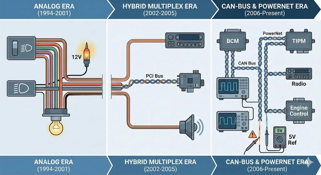
The Evolution from Analog to Digital
The history of the Dodge Ram's wiring can be categorized into three distinct electrical eras. Understanding which era a specific truck falls into is the first step in successful diagnosis and modification.
The Analog Era (1994–2001)
In the Second Generation Ram, the electrical system was predominantly analog. When a driver turned the headlight switch, a physical copper contact closed, sending 12-volt battery current directly through the wire to the headlight bulb. The wire color (e.g., Light Green for low beams) represented a direct power path. Diagnosis in this era was straightforward: a test light or multimeter showing 0V meant a broken wire or blown fuse. The color codes in this era remained relatively consistent with traditional Chrysler standards, utilizing solid colors with tracers to differentiate circuits.
The Hybrid Multiplex Era (2002–2005)
With the introduction of the Third Generation Ram, Dodge began implementing the PCI (Programmable Communication Interface) Bus. This was a transitional period. While many high-current circuits (like starter solenoids) remained analog, the communication between modules began to occur over a single-wire data bus. This era introduced the complexity of "Hybrid" wiring, where a radio harness might contain both a physical 12V ignition wire and a PCI bus data wire. The wire colors began to shift to accommodate the growing number of sensors and modules.
The CAN-Bus & PowerNet Era (2006–Present)
The watershed moment in Ram electrical history occurred in 2006 with the full adoption of the CAN (Controller Area Network) Bus architecture and the TIPM. In this modern architecture, switches often no longer control power directly. Instead, a switch (like the window switch) sends a low-voltage digital signal to a control module (like the BCM), which then activates a relay or solid-state driver to send power to the motor.
- Implication for Wire Identification: A wire color in the dashboard may no longer carry 12 volts. Instead, it might carry a 5-volt reference signal or a digital data stream. Probing a white/orange CAN-Bus wire with a traditional incandescent test light can draw too much current, potentially frying the sensitive drivers in the BCM.
- The Disappearing Accessory Wire: One of the most significant changes in this era, specifically for audio installers, was the removal of the switched 12V accessory wire from the radio harness. The radio now relies on a digital "wake-up" command, necessitating specialized interface harnesses for aftermarket installations.
The Role of the Totally Integrated Power Module (TIPM)
Central to the wiring of Gen 3 (late) and Gen 4 Rams is the TIPM. This intelligent fuse box does more than protect circuits; it manages them.
- Virtual Fusing: The TIPM can detect short circuits and cut power to a specific line without blowing a physical fuse. It resets only after a specific number of ignition cycles or a scan tool reset.
- Implication for Wiring: If a wire (e.g., the Left Low Beam) shows no voltage, it may not be a wiring fault but a logic shutdown. Identifying the correct wire color is only half the battle; ensuring the TIPM has enabled the output is the other.
1.3 Pulse Width Modulation (PWM) Explained
In Gen 4 and Gen 5 Rams, the lighting circuits (Headlights, Tail Lights) utilize PWM.
- Mechanism: Instead of a steady 12V DC current, the BCM sends power in rapid pulses (turning on and off hundreds of times per second). This allows the truck to use a single filament bulb for two functions (e.g., a bright Brake light at 100% duty cycle and a dimmer Running light at 30% duty cycle) or to use 12V bulbs in a 14V charging system without burning them out.
- Wiring Consequence: When measuring these wires with a multimeter, you may see fluctuating voltages (e.g., 9V or 10V) rather than a solid 12V. This is not a voltage drop; it is the average voltage of the pulse train. This phenomenon is the primary reason why installing LED bulbs often requires "anti-flicker" capacitors—the LED reacts fast enough to show the off-pulses, which the human eye perceives as a strobe effect.
Stereo & Infotainment Wiring Systems
The most frequent interaction owners have with their truck's wiring is during the upgrade of the audio system. The Ram platform has seen a diverse array of audio configurations, from basic 4-speaker setups to complex 19-speaker Harman Kardon systems with Active Noise Cancellation (ANC).
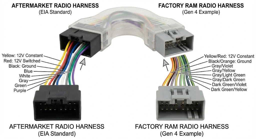
The EIA Standard vs. Factory Reality
A critical distinction must be made between Aftermarket (EIA) wire colors and Factory (OEM) wire colors.
- EIA Standard: The industry-standard color code used by aftermarket radio manufacturers (Alpine, Kenwood, Pioneer) and harness adapter manufacturers (Metra, Scosche, PAC).
- OEM Standard: The wire colors actually found in the truck's dashboard, which vary by year and trim.
Analysis: The goal of any installation is to bridge these two standards. You never cut the factory plug off; you buy an adapter harness that plugs into the factory plug and provides EIA-colored wires to match your new radio.
Table 1: The EIA Aftermarket Color Code Standard
This is what your new radio's harness will look like.
| Wire Color | Function | Polarity | Notes |
| Yellow | Battery Constant | +12V | Memory retention; always live. |
| Red | Accessory / Ignition | +12V | Switched power; live only when key is ON. |
| Black | Ground | Chassis | Essential for completing the circuit. |
| Blue | Power Antenna | +12V | Active only in AM/FM mode (usually). |
| Blue/White | Amp Turn-On | +12V | Triggers factory or aftermarket amplifiers. |
| Orange | Illumination | +12V | Signal from headlight switch (On/Off). |
| Orange/White | Dimmer | Variable | 0-12V signal for screen dimming. |
| White | Left Front Speaker | (+) | |
| White/Black | Left Front Speaker | (-) | |
| Gray | Right Front Speaker | (+) | |
| Gray/Black | Right Front Speaker | (-) | |
| Green | Left Rear Speaker | (+) | |
| Green/Black | Left Rear Speaker | (-) | |
| Purple | Right Rear Speaker | (+) | |
| Purple/Black | Right Rear Speaker | (-) |
Source:
Generation 2 Audio Wiring (1994–2001)
The Gen 2 Ram features a classic DIN or 1.5-DIN dashboard. The wiring is analog, but the "Infinity" premium sound system introduces the first layer of complexity: a factory amplifier.
Factory Harness Color Codes (Truck Side):
- 12V Constant (Battery): Pink or Red/White.
- 12V Switched (Ignition): Brown/Red or Red/Black.
- Ground: Black (Often a braided strap or attached to the chassis metal behind the dash).
- Illumination: Orange or Black/Yellow.
- Dimmer: Orange/White. Warning: Do not ground this wire or connect it to the radio's black wire; it controls the instrument cluster rheostat and will blow the "IOD" fuse if grounded.
- Amp Remote: Dark Green/Red (Found in Infinity systems).
The Infinity Amplifier Challenge:
In 1998-2001 models equipped with the Infinity system, the amplifiers are mounted individually on the front door speakers. They require a specific "turn-on" signal.
- Critical Insight: When installing an aftermarket radio, the Blue/White wire from the new radio must be connected to the factory Dark Green/Red wire. Failure to do so results in the radio powering up but producing zero sound.
- Speaker Wires:
- Left Front: Light Green/Red (+) & Light Green/Dark Green (-).
- Right Front: Light Blue/Violet (+) & Light Blue/Black (-).
- Left Rear: White/Red (+) & White/Black (-).
- Right Rear: Tan/Violet (+) & Tan/Black (-).
Generation 3 Audio Wiring (2002–2008)
This generation is bisected by the CAN-Bus implementation in 2006.
Phase 1: The PCI Era (2002–2005)
These trucks retain a physical 12V switched wire in the harness.
- Constant 12V: Pink.
- Switched 12V: Brown/Red.
- Ground: Black/Dark Green.
- Illumination: Orange/Dark Blue.
- Dimmer: Orange/White.
- Antenna: The antenna plug is a standard Motorola type.
Phase 2: The CAN-Bus Era (2006–2008)
In 2006, the radio connector changed, and the electrical logic shifted.
- The Missing Wire: There is NO 12V switched accessory wire in the factory harness. The factory radio turns on via a data signal.
- The Interface Module Solution: Installers must use a module (e.g., PAC RP4-CH11) that reads the CAN signal and creates a synthetic Red 12V wire.
- The "Cheap" Workaround: If avoiding the module, one must run a wire to the cigarette lighter or fuse box to find a keyed power source. The cigarette lighter wire is typically Blue/Pink or Light Blue/Yellow.
- Factory Wire Colors (2006+):
- Constant 12V: Gray/Red.
- Ground: Black/Dark Green.
- CAN Bus (+): White/Orange.
- CAN Bus (-): White.
- Left Front Speaker: Dark Green/Yellow (+) & Dark Green/Light Blue (-).
- Right Front Speaker: Gray/Yellow (+) & Gray/Light Blue (-).
- Left Rear Speaker: Gray/Light Green (+) & Gray/Dark Green (-).
- Right Rear Speaker: Dark Green/Light Green (+) & Dark Green/Gray (-).
Generation 4 Audio Wiring (2009–2018)
The Gen 4 system integrates deeply with Uconnect. The head unit is no longer just a radio; it controls vehicle settings, climate (in 8.4" screens), and heated seats.
Harness Variations:
- Base System (4-Speaker): Direct wiring from radio to speakers.
- Alpine System (9-Speaker): The radio sends a fixed 2-channel signal to an amplifier (usually under the dash or rear seat). The amplifier handles crossover and distribution.
- Harman Kardon (19-Speaker): Uses a digital coax cable (A2B bus) or similar high-speed link.
Gen 4 Wire Color Code Chart (Base/Alpine Input):
- Constant 12V: Yellow/Red.
- Ground: Black or Black/Orange.
- Front Left: Gray/Violet (+) & Gray/Yellow (-).
- Front Right: Dark Green/Violet (+) & Dark Green/Yellow (-).
- Rear Left: Gray/Light Green (+) & Gray/Dark Green (-).
- Rear Right: Dark Green/Light Green (+) & Dark Green/Gray (-).
The Reverse Camera Trap (PAC RP4-CH21 Harness): A specific issue documented in installation research involves the backup camera trigger on 2013+ trucks using the PAC interface.
- Confusion: On the PAC module side, the Purple/White wire is not Reverse; it is Vehicle Speed Sense (VSS). The Green wire on the PAC module is the Reverse Output.
- Correction: The installer must connect the radio's Purple/White (Reverse Input) wire to the PAC module's Green wire. Connecting color-for-color (Purple/White to Purple/White) will result in the camera failing to trigger or triggering erratically based on speed.
Generation 5 Audio Wiring (2019–Present)
The 2019+ Ram 1500 (DT platform) introduces Active Noise Cancellation (ANC) as a standard feature on many trims.
- ANC Microphones: Located in the headliner.
- The Subwoofer Issue: Installing aftermarket subwoofers requires bypassing the ANC system. If not bypassed, the ANC microphones will detect the subwoofer's bass as "noise" and generate an anti-phase signal, causing a feedback loop (loud hum/drone).
- Bypass Strategy: An ANC bypass harness is installed at the amplifier location (under the driver's seat) to disconnect the microphones while keeping the speakers active.
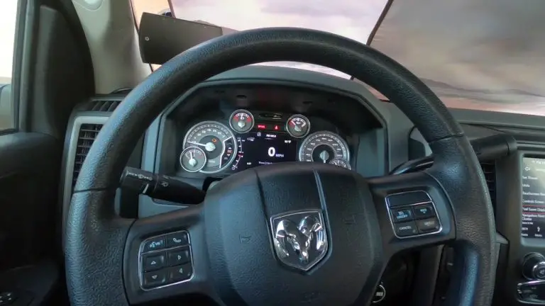
Ignition & Remote Start Integration
Installing a remote starter or security system requires tapping into the vehicle's ignition harness. This is the "spinal cord" of the truck.
3.1 Ignition Harness Color Codes by Generation
Table 2: Ignition Switch Matrix
| Function | Gen 2 (1994-2001) | Gen 3 (2002-2008) | Gen 4 (2009-2018) | Gen 5 (2019+) |
| 12V Constant | Red & Pink/Black | Red or Pink/White | Red or Pink (High Current) | Red (PDC Feed) |
| Starter | Yellow | Yellow/Gray | Pink/White (MUX) | N/A (Push Button) |
| Ignition 1 | Dark Blue | Pink/White | Pink/White (MUX) | Pink/White (Hub) |
| Ignition 2 | Black/White | Pink/Green | N/A | N/A |
| Accessory | Black/Orange | Black/Orange | Violet/Brown (MUX) | Violet/Brown |
| Key Sense | Orange | Blue | Violet/Tan | N/A (RFID) |
The Multiplex (MUX) Revolution
Starting in the late Gen 3 era and becoming standard in Gen 4, Dodge moved to a "MUX" ignition switch.
- The Mechanism: Instead of separate heavy-gauge wires for Ignition, Accessory, and Start, the switch uses a single wire (often Pink/White) carrying a low-current signal.
- Resistance Values: The switch changes the resistance to ground to indicate position:
- Acc: ~560 Ohms.
- Run: ~220 Ohms.
- Start: ~75 Ohms.
- Installation Impact: You cannot simply splice a 12V output from a remote start brain to the "Start" wire. You must cut the MUX wire and insert relays with precise resistors to mimic the key's resistance, OR use a data integration module (like iDatalink ADS-ALCA) that communicates the start command digitally via the CAN bus (White/Orange & White wires).
Door Triggers & Security
Identifying door triggers is essential for alarm installation.
- Gen 4/5 Color Codes: The door status is often read via a MUX circuit or individual triggers at the BCM.
- Driver Front Door: Violet.
- Passenger Front Door: Violet/White.
- Driver Rear Door: Violet/Gray.
- Passenger Rear Door: Violet/Yellow.
- Dome Light Supervision: Yellow/White (Gen 4).
Exterior Lighting & Signaling

Lighting is a critical safety system and a popular area for customization. The transition to LED technology in the aftermarket has made understanding Ram lighting wiring—and the "Bulb Out" detection system—crucial.
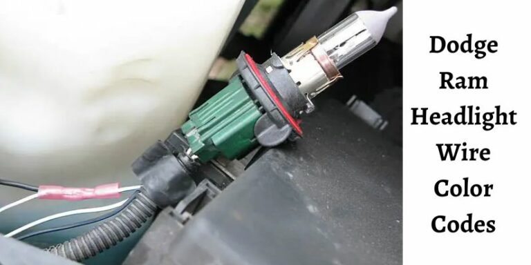
Headlight Wiring: Halogen, HID, and LED
The Ram's headlight circuit is notorious for its sensitivity. The Central Body Controller (CBC) or BCM monitors current draw. If it detects a variance (like the lower draw of an LED bulb), it cuts power to the circuit to "protect" it, assuming a bulb failure or short.
Table 3: Headlight Wire Colors (Gen 4 Quad/Dual Lamps)
| Function | Driver Side Color | Passenger Side Color | Notes |
| Low Beam (+) | White/Dark Blue | White/Tan | PWM Signal (Pulsed) |
| High Beam (+) | White/Light Green | White/Gray | PWM Signal |
| Turn Signal (+) | White/Light Green | White/Yellow | |
| Park/Marker (+) | White/Yellow | White/Yellow | |
| Ground (-) | Black | Black | Check G100/G101 grounds |
The PWM Flicker Issue:
Because the low beam voltage is pulsed (PWM), connecting a relay harness for HIDs or LEDs often results in "relay buzz" or strobe-light flickering.
- The Solution: A capacitor-link harness (often called a "CAN-Bus Decoder" or "Anti-Flicker Module") is required between the factory plug and the new light. The capacitor stores the energy during the "on" pulse and discharges it during the "off" pulse, creating a smooth DC voltage for the new light.
Tail Light Wiring & The "BMW Connector"
For the 2019+ (Gen 5) Ram, a specific issue has emerged regarding replacement tail light connectors. The 6-pin connector used is physically identical to a connector used on some BMWs, leading to the sale of "universal" pigtails online.
- The Hazard: The pinout of the BMW pigtail is different from the Ram. Specifically, the ground wire position is swapped.
- Result: Plugging in the generic pigtail causes the brake light circuit to feed back into the ground, blowing fuses or damaging the BCM.
Gen 5 Ram Tail Light Pinout (Factory):
- Brown: Parking / Running Lights.
- Red/White: Brake Lights.
- Black/Yellow: Turn Signal.
- White/Green: Reverse Light.
- Black: Ground (Chassis).
- (Empty or Blind Spot Monitor Data in some trims).
Trailer Towing Wiring
Ram trucks are workhorses, and trailer wiring is a frequent service point. The wiring follows the SAE J2863 standard for the 7-way connector, but confusion often arises from the difference between "Traditional/RV" colors and "SAE" colors.
Table 4: 7-Way Trailer Connector Pinout (Vehicle Side)
Looking at the back of the truck.
| Pin Position | Function | SAE Color (Ram Factory) | Traditional RV Color |
| 1:00 | +12V Battery Charge | Red or Black/Orange | Black |
| 3:00 | Right Turn / Stop | Green | Brown |
| 5:00 | Electric Brakes | Blue | Blue |
| 7:00 | Ground | White | White |
| 9:00 | Left Turn / Stop | Yellow | Red |
| 11:00 | Tail / Running | Brown | Green |
| Center | Reverse / Aux | Purple or Black | Yellow |
The Missing Blue Wire (Gen 3/4):
Many owners find the Blue brake controller wire is not connected under the dash.
- Location: In trucks without the factory Integrated Trailer Brake Controller (ITBM), the blue wire terminates in a white or gray connector near the parking brake pedal or kick panel.
- Connection: An aftermarket brake controller (like a Tekonsha Prodigy) must be wired to this pigtail.
- Ram Pigtail Colors:
- Red or Black/Red: 12V Power (Check fuse M29/M30 in PDC).
- White: Ground.
- Blue: Brake Output to Trailer.
- Red/White: Brake Pedal Signal (Cold Side).
- Ram Pigtail Colors:
Upfitter Switches & Gen 5 Auxiliary Power
The 2019+ Ram 1500 (and Heavy Duty) trucks introduced a vastly improved Upfitter Switch bank. These switches are no longer just simple toggles; they are programmable logic inputs that control relays in a dedicated Auxiliary Power Distribution Center (Aux PDC).
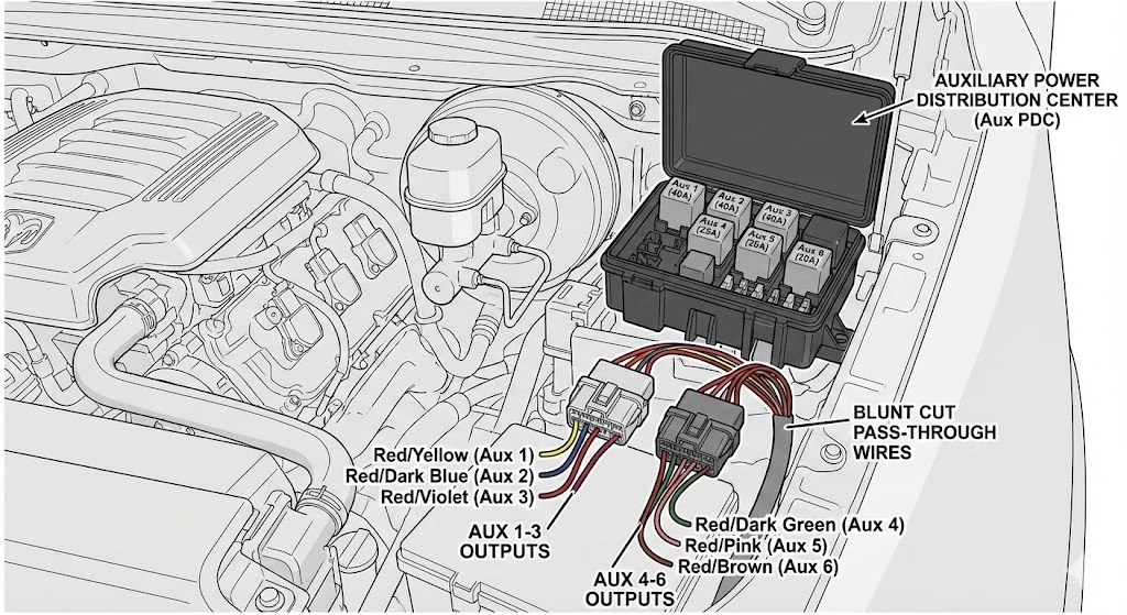
The Aux PDC Location & Layout
The Aux PDC is located under the hood, on the driver's side, near the firewall. It is a separate box from the main fuse box.
- Relays: Contains relays for Aux 1 through Aux 6.
- Fuses:
- Aux 1, 2, 3: 40A Max (High Current).
- Aux 4: 25A Max.
- Aux 5, 6: 20A Max (Low Current).
- Note: Aux 6 is often shared with the PTO (Power Take-Off) relay on HD trucks.
Connecting to the Upfitter Switches
A common frustration is looking for these wires under the dashboard. They are not there. The output of the relays terminates in two connectors under the Aux PDC in the engine bay.
Connector Details:
- Light Gray Connector: Contains outputs for Aux 1, 2, 3.
- Dark Gray Connector: Contains outputs for Aux 4, 5, 6.
- Connection Method: The truck comes with a "baggie" of loose terminals or pigtails in the glovebox. You must crimp your accessory wire to these terminals and insert them into the connectors under the PDC.
Upfitter Output Wire Colors (At the PDC):
- Aux 1: Red/Yellow (Circuit A962).
- Aux 2: Red/Dark Blue (Circuit A963).
- Aux 3: Red/Violet (Circuit A964).
- Aux 4: Red/Dark Green (Circuit A965).
- Aux 5: Red/Pink (Circuit A966).
- Aux 6: Red/Brown (Circuit A967).
The "Blunt Cut" Pass-Through Wires
To get these signals (or other aftermarket wires) through the firewall without drilling and risking water leaks, Ram provides "Blunt Cut" pass-through wires.
- Identification: A bundle of 4 wires with heat-shrinked ends, taped to the main harness.
- Engine Side: Near the brake booster/master cylinder.
- Cab Side: Near the parking brake pedal mechanism.
- Usage: These wires are not connected to anything at either end. They are essentially extension cords. You connect your Aux 1 output (Red/Yellow) to the engine-side pass-through wire, and then connect your accessory to the corresponding cab-side pass-through wire.
VSIM (Vehicle System Interface Module)
For fleet and commercial applications, the VSIM provides deeper integration. It is a module located under the dash that provides hard-wired inputs and outputs for data bus signals (e.g., Door Open status, Vehicle Speed, Park Brake status) without needing to tap into the CAN bus directly. This protects the main vehicle network from interference by aftermarket equipment.
Troubleshooting & Best Practices
Even with the correct color codes, electrical work on Ram trucks requires specific techniques to avoid "Gremlins."
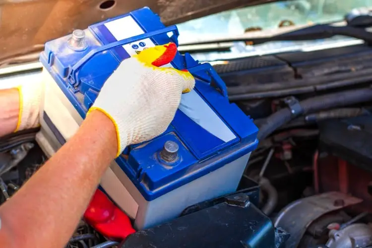
Grounding: The Foundation
Dodge Rams are notoriously sensitive to poor grounds.
- Symptoms: Flickering lights, phantom wiper operation, "No Bus" messages on the cluster.
- Critical Ground Points:
- G101 (Engine Bay): Main battery-to-body ground.
- G200/G202 (Kick Panels): Dashboard and Radio grounds.
- G300+ (Rear Frame): Tail lights and fuel pump.
- Best Practice: Never rely on the factory black wire in a harness for high-current aftermarket devices (like amps or light bars). Run a dedicated ground cable to a clean chassis bolt, scraping away paint to ensure metal-to-metal contact.
Splicing: The "Soldering" vs. "Crimp" Debate
- Interior (Dry): Quality crimp connectors or Posi-Taps are acceptable.
- Exterior/Engine (Wet/Vibration): Soldering with adhesive-lined heat shrink is the only long-term solution. The "green crust" corrosion (copper oxide) that forms in unsealed crimps is the leading cause of trailer light failure.
- Avoid: "Scotch-Lock" or "Vampire" clips that cut into the wire insulation. These create a weak point that eventually corrodes or breaks due to vibration.
6.3 TIPM Resets
If you accidentally short a wire and the circuit goes dead (but the fuse is fine), you have likely tripped a driver in the TIPM.
- Soft Reset: Disconnect both battery cables and touch them together (capacitive discharge) for 10 minutes. This drains all residual power from the modules.
- Hard Reset: Requires a high-level scan tool (WiTech, Snap-On, or AlfaOBD) to clear the "Short to Ground" fault code in the TIPM/BCM.
Handling Airbag (SRS) Wiring
Warning: Airbag wiring is universally Yellow or wrapped in Yellow Tape. Never probe, splice, or test these wires. The voltage from a multimeter can deploy the bag.
Conclusion
The wiring of a Dodge Ram is a sophisticated network that balances power delivery with digital communication. From the simple analog circuits of the 1990s to the complex, logic-driven PowerNet systems of today, the evolution of these trucks demands a higher level of technical understanding from the installer.
By utilizing the color codes and architectural insights provided in this report, technicians can navigate the harness with confidence. Whether it is ensuring the correct "wake-up" signal for a Gen 3 radio, bypassing the PWM flicker on a Gen 4 headlight, or utilizing the dedicated Upfitter relays on a Gen 5, the key to success lies in respecting the system's logic. Remember: verify every wire with a digital multimeter, ensure uncompromising grounds, and when in doubt, consult the specific diagram for your trim level.