2015 Chevy Silverado Wiring Diagram: Mapped Out by K2XX Platform Specs

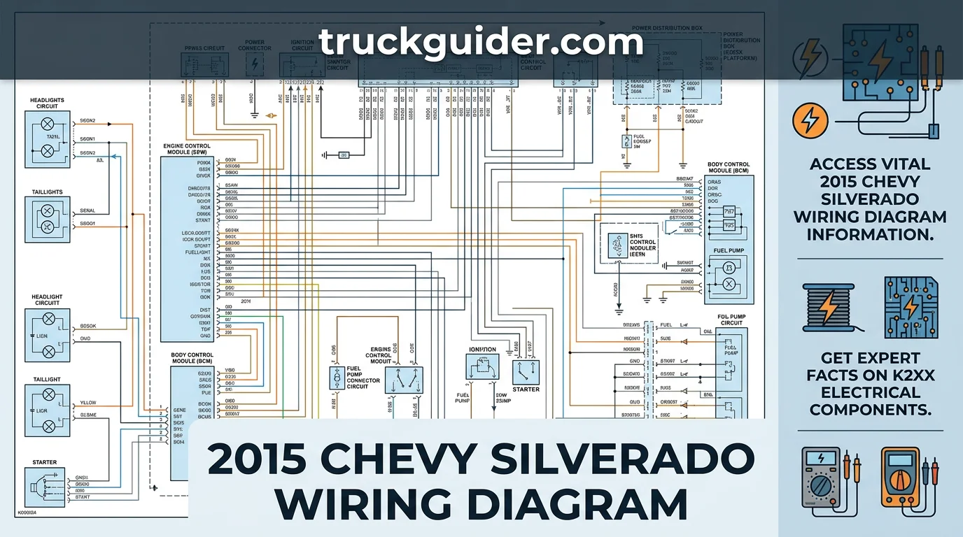
The 2015 Chevy Silverado wiring diagram provides the specific circuit paths, ground points, and connector pin-outs required to diagnose and repair your truck’s electrical systems. This guide organizes the K2XX platform’s complex harness data into actionable references, ensuring you can identify wire colors, interpret GM-specific connector schemas, and safely perform circuit testing without risking damage to sensitive control modules or the vehicle’s onboard communication network.
2015 Chevy Silverado Wiring Diagram Main Reference Chart
Recommended Best Deal Products


How to Read This Chart
The chart above identifies central power distribution points for the 2015 Silverado. The “Module/Block” column names the specific hardware, while “Physical Location” provides the general area for inspection. Ensure your system voltage reads between 12 and 14.5 Volts before testing any individual circuit.

The “Primary Function” labels help distinguish between high-current nodes like the UEC, which manages direct battery power for heavy components, and logic modules like the BCM, which handle sensor signals and data communication. Always verify your vehicle’s specific RPO codes against your owner’s manual, as features like trailering packages or diesel engines may shift module connections.

When using these nodes for troubleshooting, focus on the “Status” column. Items marked as “Verified” are standard across all 2015 light-duty Silverado 1500 platforms. Items marked “Verify for exact configuration” indicate that placement or pin-out intensity may vary based on trim levels, accessory packages, or engine types (V6 vs. V8). Always cross-reference with your specific vehicle build sheet.
The 2015 Silverado relies on these central nodes to manage the K2XX platform’s complex electrical architecture. The Underhood Electrical Center (UEC) acts as the primary clearinghouse for main power, while the Instrument Panel (IP) block acts as a secondary bridge for cabin-specific devices and body-related electrical loads.
Successful diagnosis requires understanding that these nodes communicate via high-speed and low-speed GMLAN serial data buses. If a system failure is detected at the BCM or ECM, check for clear communication signals before assuming a wiring harness break. Ensure your diagnostic tools are set to DC Volts when probing these modules.
Identifying Your Specific 2015 Silverado Electrical Configuration
Using a generic wiring diagram for a 2015 Chevy Silverado is a common source of diagnostic error. Because GM utilizes platform-specific architecture, you must verify your vehicle’s unique build configuration before attempting any circuit repairs or testing.
Wiring complexity varies significantly based on trim levels, accessory packages, and production dates. A Work Truck trim will lack the integrated modules found in an LTZ or High Country, meaning wire colors and pin-out locations often differ entirely between these models.
Locating Your VIN and RPO Sticker
The most reliable way to match your truck to the correct diagram is via the Service Parts Identification (SPID) sticker. On the 2015 Silverado, this sticker is typically located inside the glove box or on the door jamb of the driver’s side.
The SPID label contains your vehicle’s unique Regular Production Option (RPO) codes. These three-character alphanumeric strings act as an equipment manifest, detailing exactly which electrical systems—such as factory remote start, trailer brake controllers, or navigation units—are installed.
Always cross-reference your specific RPO codes against the diagram notes. If your diagram shows a circuit for a trailer brake controller (RPO JL1), but your build sheet does not list this code, you are likely looking at a secondary harness that does not exist in your vehicle.
Matching Engine Wiring to Harness Options
Beyond interior trim, engine-specific harness layouts are critical. The 2015 Silverado featured three distinct EcoTec3 engine options—the 4.3L V6, 5.3L V8, and 6.2L V8—each requiring its own dedicated Engine Control Module (ECM) communication pin-out.
Even if two trucks share the same engine, transmission configurations or transfer case options can change the wiring loom geometry. A 4WD truck uses additional wiring for the transfer case encoder motor that is entirely absent in a 2WD configuration.
Before performing continuity tests, use your VIN to confirm the engine and transmission variant in a decoder tool. Failure to match the harness layout to the powertrain will result in incorrect voltage readings and potential damage to sensitive electronic control units.
2015 Chevy Silverado Wiring Diagram Evolution: K2XX Platform
Recommended Best Deal Products


The 2015 Chevrolet Silverado is a core member of the K2XX vehicle architecture, which spanned the 2014 through 2016 model years. This platform unified the electrical backbone, utilizing a centralized Controller Area Network (CAN bus) to manage communication between vehicle modules. Understanding this structural baseline is critical for accurate diagnostic work.
Because the K2XX architecture remained stable during these years, many basic wiring paths are consistent. However, assuming that a diagram from one year is perfectly interchangeable with another is a common diagnostic error. Minor changes in module firmware and wire routing were implemented to address specific field performance issues.
2014 vs 2015 Silverado Wiring Differences
The 2014 model year served as the inaugural launch for the K2XX platform, while the 2015 model acted as a period of refinement. Most primary wiring diagrams for the powertrain and chassis remain identical across these two years. Changes between them are largely isolated to infotainment system revisions and minor accessory circuit modifications.
For instance, the 2015 model introduced specific adjustments to the OnStar and telematics integration that were absent in 2014. If you attempt to use a 2014 diagram for a 2015 infotainment issue, you may find discrepancies in the pin-out of the Data Link Connector or the auxiliary high-speed CAN bus connections.
Always verify the RPO (Regular Production Option) codes on your vehicle’s service parts identification sticker. Even within the same model year, varying trim levels or optional equipment packages can significantly alter the required wiring diagram for safety and comfort systems.
2015 vs 2016 Electronic Integration Changes
The shift from 2015 to 2016 marked a significant increase in safety sensor complexity. While the core wiring for the engine and transmission remained largely unchanged, the 2016 model introduced updated advanced driver-assistance systems that required additional signal wires in the body harness.
In 2015, safety features like lane-keeping assist and advanced collision mitigation were less prevalent or utilized simpler module protocols. By 2016, these systems began integrating more heavily into the main vehicle CAN bus. This required the addition of extra shielded twisted-pair cabling to prevent signal interference during high-speed data transmission.
Consequently, 2015 diagrams often lack the specific branch circuits for these updated 2016 safety sensors. Relying on a 2016 schematic for a 2015 vehicle may lead you to look for wires or connectors that simply do not exist on your specific chassis build, creating unnecessary confusion during your electrical troubleshooting process.
Safety Guidelines for Testing GM Electrical Circuits
Working on the K2XX platform of the 2015 Chevy Silverado requires strict adherence to electronic safety protocols. Before performing any probing or harness manipulation, battery disconnection is mandatory. Disconnecting the negative terminal prevents accidental short circuits that can instantly fry sensitive vehicle control modules.
Never bypass this step when accessing the body control module (BCM) or engine control module (ECM). High-voltage spikes caused by loose connections during testing can propagate through the vehicle’s entire network. Always wait at least two minutes after disconnecting the battery to allow capacitors in the airbag and powertrain modules to discharge safely.
Why High-Draw Test Lights Damage Modules
Traditional incandescent test lights are inherently dangerous for the 2015 Silverado’s multiplexed electrical architecture. These old-school tools draw significant current—often 500mA to 2A—to illuminate their bulbs. Modern GM logic circuits are designed for low-current signal transmission and cannot handle this surge.
If you connect a high-draw test light to a CAN bus communication wire, you are essentially creating a massive localized current drain. This will likely trigger internal faults in the module or cause permanent damage to the driver chips on the circuit board. Once a module’s communication transceiver is damaged, it will stop sending or receiving data entirely.
To avoid this, use a high-impedance digital multimeter (DMM) for all diagnostic testing. A quality DMM has an internal resistance of at least 10 megaohms, which ensures negligible current flow. This allows you to verify voltage signals on communication lines without interfering with the data integrity of the vehicle’s complex sensor network.
For example, probing a CAN bus harness with a test light can bridge two high-speed data lines. This creates a short that wipes out all data transmission, causing an immediate “Communication Lost” error across the dashboard. This mistake often forces an expensive replacement of the module, which must then be programmed at a dealership.
Avoiding Generic Manual Pitfalls
Relying on generic repair manuals, such as standard Haynes or Chilton guides, introduces significant diagnostic risk. These manuals often provide generalized wiring diagrams that do not account for the specific engine, trim level, or regional build codes found in your 2015 Silverado.
Generic diagrams may mislabel pin-outs or overlook mid-year production changes in wire colors. Probing a wire based on a generic assumption often leads to the wrong circuit being energized or grounded. In the K2XX platform, where many wires share similar insulation colors, accuracy is not optional—it is a critical requirement.
Always verify your specific circuit against the official GM Service Information (SI) or a verified VIN-specific wiring schematic. If the wire color or pin location does not match your vehicle’s physical connector exactly, stop testing immediately. Guessing based on a generalized manual is a leading cause of fried electronic control units.
When in doubt, use a breakout box or dedicated test leads to tap into the harness. These tools provide a secure, low-resistance interface for your multimeter probes. This eliminates the risk of piercing wire insulation or shorting pins together, ensuring the structural integrity of your Silverado’s harness remains intact during the troubleshooting process.
Interpreting GM Wire Color Codes and Connector Pin-outs
Recommended Best Deal Products


| Circuit Type | Typical Color Range | Function Indicator |
|---|---|---|
| Ground | Black / Black-White | Chassis Reference |
| Signal Ground | Tan / Brown / Yellow | Sensor Return |
| Battery Positive | Red / Red-White | Constant 12V |
| Ignition Feed | Pink / Brown | Switched 12V |
How to Read This Chart
This table outlines standard GM wire identification protocols for the 2015 Silverado. The Circuit Type column categorizes common power and ground flows, while the Typical Color Range provides the baseline industry standard.
Note that the Function Indicator column is critical, as it describes the component’s role in the K2XX architecture. Users must always verify these codes against the specific schematic index for their engine and trim level, as variations exist.
Decoding GM Wire Color Patterns
A primary pitfall for technicians is the assumption that wire colors remain consistent across different harness locations. In the 2015 Silverado, GM frequently reuses specific color codes for entirely unrelated electrical circuits.
For instance, a solid white wire might function as a dedicated ground path in a lighting circuit, yet act as a sensitive serial data signal in an infotainment or powertrain module circuit. Never rely on color alone to identify a wire.
Always verify the circuit identification tag or the schematic callout before piercing or cutting insulation. When looking at a diagram, focus on the alphanumeric circuit code printed next to the wire rather than the color swatch itself.
Mastering Terminal Pin-out Diagrams
Connector pin-outs provide the definitive roadmap for your wiring harness. Every GM connector features a numbered grid or sequence stamped directly onto the housing, usually visible on the wire-entry side or the mating face.
When reviewing a pin-out diagram, identify the connector orientation by finding the locking tab or “keying” feature. This physical marker ensures you are not reading the diagram backward, which is the most common cause of short circuits during repairs.
Distinguish carefully between chassis grounds and signal grounds. A chassis ground terminates to the vehicle frame to complete a high-amperage power loop, while a signal ground—often identified by unique insulation stripes—returns to an ECU to provide a clean reference for sensors.
If you encounter a wire that does not match the diagram, check for aftermarket equipment or previous harness repairs. Use a digital multimeter to confirm voltage or continuity to ground before finalizing any connection changes to avoid damaging sensitive K2XX modules.
Troubleshooting 2015 Chevy Silverado Wiring Diagram Faults
Electrical diagnostics on the K2XX platform require a systematic approach to isolate power-draining components. Always begin by verifying the battery state-of-charge and load capacity before assuming a wiring fault. Intermittent failures often stem from loose connectors, oxidized grounds, or poorly installed aftermarket accessories that bypass factory protection.
Locating Parasitic Battery Drains
A parasitic drain occurs when a circuit continues to draw current after the ignition is switched off and the vehicle has entered “sleep mode.” For the 2015 Silverado, the control modules typically enter sleep mode within 10 to 20 minutes. Ensure all doors are latched and accessories are off before starting your test.
To isolate the drain, use a digital multimeter set to measure DC Amps in series between the negative battery terminal and the cable. A normal quiescent current for this model year is typically under 30-50mA. If readings are higher, you must systematically pull fuses from the instrument panel or under-hood fuse blocks one by one.
When the multimeter reading drops significantly after pulling a specific fuse, you have identified the circuit responsible for the draw. Before assuming a factory wiring fault, inspect that circuit for aftermarket additions such as remote starts, aftermarket lighting, or security systems. These items are the most common cause of high parasitic loads on these trucks.
📋
Step-by-Step Isolation Process
Disconnect the negative terminal and place your multimeter leads between the post and the cable clamp to measure total vehicle current draw.
Allow the truck to sit for at least 20 minutes. Verify the multimeter reading is stable once all electronic control units have timed out.
Pull one fuse at a time. A significant drop in the amperage reading indicates the faulty circuit or accessory is controlled by that specific fuse.
Testing for Open and Short Circuits
An open circuit occurs when there is a break in the path of electricity, preventing current from reaching the load. Common symptoms include a device that simply refuses to power on. Use a multimeter set to Ohms to test for continuity between the fuse terminal and the component connector; infinite resistance confirms an open line.
Conversely, a short circuit occurs when current finds a path to ground before reaching the intended component. This usually results in a blown fuse. To identify a short, test for continuity between the load side of the fuse socket and the chassis ground. If the meter beeps, you have a direct short to ground in that specific wiring harness.
When searching for these faults, inspect common ground failure points. On the 2015 Silverado, these are often located near the chassis frame rails or engine block. Corrosion at these junctions creates high resistance, which causes flickering lights or erratic sensor data. Always clean ground terminals to bare metal and verify the connection is tight to ensure a reliable path for return current.
Key Takeaways
-
✓
Locate specific schematics for your truck’s unique trim and engine configuration. -
✓
Master the K2XX platform electrical layout for faster fault isolation. -
✓
Understand GM-standard wire color-coding to prevent cross-circuit damage. -
✓
Follow rigorous safety protocols when probing high-voltage or sensitive ECU circuits. -
✓
Utilize step-by-step diagnostic methods to resolve common electrical gremlins.
❓ Frequently Asked Questions
1
What is the 2015 Chevy Silverado wiring diagram?
The 2015 Chevy Silverado wiring diagram is a technical schematic showing how electrical components connect within the K2XX platform. It provides necessary info on wire routing, connector pin-outs, and grounding paths, serving as the primary map for mechanics to diagnose and repair electrical issues across the truck’s various sub-systems.
2
How does 2015 Chevy Silverado wiring work?
The electrical system relies on a CAN-bus architecture where various control modules communicate via low-voltage signals. Wiring connects sensors, actuators, and the BCM (Body Control Module) using standardized color-coded circuits. Understanding these details is vital for interpreting how power flows and signals transmit throughout the truck’s complex internal network.
3
Why is the 2015 Chevy Silverado wiring diagram important?
Having the correct diagram is critical because the 2015 model year features specific K2XX electronic configurations. Without accurate insights into these circuits, technicians risk blowing fuses, damaging computer modules, or triggering false trouble codes. It provides the essential facts required to troubleshoot effectively without guessing at wiring paths.
4
What are the benefits of using a wiring diagram?
The primary benefits include reduced diagnostic time, increased repair accuracy, and enhanced safety. By following a proven diagram, you avoid potential short circuits and ensure that aftermarket installations integrate seamlessly with existing vehicle electronics, preserving the longevity of your Silverado’s electrical components and preventing costly dealership repairs.
5
How can I get started with electrical troubleshooting?
Start by identifying your specific trim and engine configuration to ensure you use the correct diagram version. Gather your digital multimeter and terminal tool kit. Once you have the relevant info and facts from your specific model’s schematic, methodically test circuits starting from the power source toward the component.
6
Where is the ground location for the headlight harness?
Typically located on the forward frame rail or radiator support near the headlights. Advise checking the specific diagram for the exact chassis ground point.
![Dodge Ram 2500 Interior [2026]](https://truckguider.com/wp-content/uploads/2026/03/featured-583ae4d5-768x768.webp)
![Ram Tradesman Vs Big Horn [2026]](https://truckguider.com/wp-content/uploads/2026/03/featured-a1247c2c-768x256.webp)
![Why Are Fog Lights Yellow? The Science of Better Visibility [2026]](https://truckguider.com/wp-content/uploads/2026/03/why-are-fog-lights-yellow-featured.webp)