3.6 Pentastar Sensor Location Diagram: 2026 Ram and Jeep

The 3.6 Pentastar sensor location diagram is easiest to understand when you separate the sensors visible above the engine from those hidden behind or below it. On the 2013 Ram 1500 3.6L Pentastar V6,
the camshaft sensors sit at the rear of the cylinder heads, the crankshaft sensor mounts low in the engine block, and the oil and knock sensors occupy the engine valley beneath the intake manifold.


This location guide uses the 2013 Ram 1500 as its main reference and compares key positions with the 2012 Jeep Wrangler JK. Confirm your model year and engine before unplugging or removing a component. Not every later Pentastar application shares an identical intake, connector, or access layout.
Location zones for the 2013 Ram 1500 reference engine. Find the right viewing angle before inspecting any connector.
Bank 1
Bank 2
Identification guide only. This is a spatial grouping schematic, not an OEM mounting drawing. Exact connector, bracket and access positions must be checked against vehicle-specific service information before removal.
- Confirm vehicleModel year, 3.6L engine and complete DTC.
- Choose viewTop, rear, underside or hidden valley.
- Find landmarkHead cover, intake, filter housing or block.
- Match connectorCheck position, plug and retaining hardware.
- Test circuitFollow service diagnostics before replacement.
What to Check Before Using a Pentastar Diagram


First, identify the engine’s front and rear. The front carries the accessory drive and faces the radiator. The rear faces the transmission and firewall.
On the longitudinal 3.6L Pentastar layout used in the reference Ram and Wrangler, Bank 1 is the passenger-side (right) cylinder bank and Bank 2 is the driver-side (left) bank. Left and right refer to the direction of travel while seated in the vehicle, not your left and right when standing in front of the open hood.



For additional engine identification details, check TruckGuider’s Ram 3.6L Pentastar engine specifications.
Where Are the Main 3.6 Pentastar Sensors Located


Use this sensor location map as the text reference for the 2013 Ram 1500 3.6L Pentastar V6. It identifies the mounting region and viewing direction, rather than suggesting every sensor is visible in one top-down view.
| Sensor | Location on Reference Engine | Best Identification View |
|---|---|---|
| Camshaft position (CMP), Bank 1 | Rear of passenger-side cylinder head cover | From above, toward firewall |
| Camshaft position (CMP), Bank 2 | Rear of driver-side cylinder head cover | From above, toward firewall |
| Crankshaft position (CKP) | Low on rear-right engine block, near transmission | From underneath |
| Manifold absolute pressure (MAP) | Upper intake manifold | From above, after identifying intake resonator |
| Intake air temperature (IAT) | Air intake resonator or inlet-air path near throttle body | From above |
| Oil pressure | Oil filter housing assembly in engine valley | Intake area, partially concealed |
| Oil temperature | Oil filter housing assembly | Intake area, partially concealed |
| Knock sensors 1 and 2 | On engine block in valley, beneath intake assemblies | Exposed only after significant disassembly |
| Engine coolant temperature (ECT) | Rear of left cylinder head, in coolant jacket | Left wheel-well access on 2013 Ram |
| Upstream and downstream oxygen sensors | Exhaust pipes around catalytic converters | From below, along exhaust |
Orientation map: Front = radiator and belt drive. Rear = firewall and transmission. Passenger/right = Bank 1. Driver/left = Bank 2. Above the engine are the intake, MAP and IAT areas. Behind the heads are the CMP sensors. Beneath the intake are the oil-filter-module and knock-sensor areas. Lower at the rear of the block is the CKP sensor.
The 2012 Wrangler has a similar general sensor arrangement, but its engine-bay packaging and access conditions are not interchangeable with those of a Ram. A 2012 Wrangler Pentastar sensor location reference is useful for comparing the major mounting areas.


Where Are Both 3.6 Pentastar Camshaft Sensors


The reference 3.6L Pentastar V6 has two physical camshaft position (CMP) sensor assemblies, one on each cylinder bank. Each is a dual-read sensor that sends position information for two camshafts. That gives the powertrain control module (PCM) four camshaft-position signals, not four separate CMP sensor housings.
Bank 1 Camshaft Sensor


Find Bank 1 on the passenger side. Look at the rear end of the cylinder-head cover, toward the transmission and firewall. The CMP sensor is attached to the head and extends through the cover. You are looking for the sensor assembly and its electrical connection, not an oil-control solenoid at the front of the head.
Bank 2 Camshaft Sensor
Bank 2 is on the driver side of this longitudinal engine. Its CMP sensor occupies the corresponding rear cylinder-head area. The firewall and adjacent harnesses can obstruct a direct view, so compare the connector and mounting point with the year-specific service illustration.
CMP Sensors Versus VVT Solenoids
A variable valve timing (VVT) oil-control solenoid changes camshaft timing by managing oil flow to an actuator. A CMP sensor measures camshaft position. The two components have different jobs and locations. A DTC mentioning “Bank 1 Sensor 2” identifies a monitored camshaft signal; it does not prove there is a second separate sensor body on that bank.

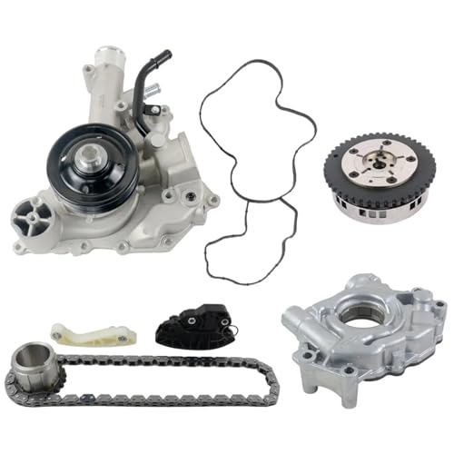


The 2013 Ram 1500 CMP diagnostic reference explicitly describes the dual-read design and rear-of-cover mounting position. That distinction matters before ordering a replacement sensor.
Where Is the 3.6 Pentastar Crankshaft Sensor


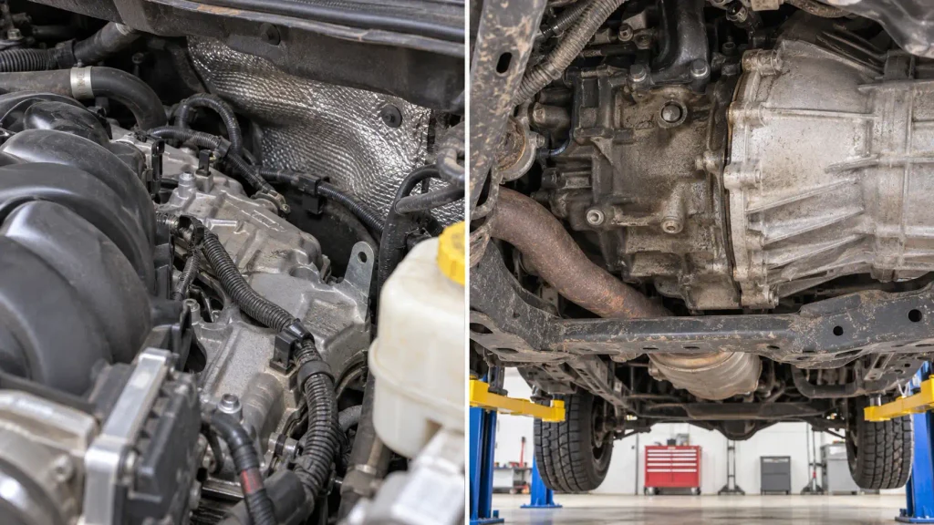
The crankshaft position (CKP) sensor mounts directly into the cylinder block, low toward the rear of the engine, near the transmission. On the 2013 Ram 1500, the service removal procedure begins by safely raising and supporting the truck. This is a lower-engine access point, not a sensor on the front timing cover.
From underneath, identify the rear engine block and look for the sensor entering the block with an electrical connector and retaining bolt.
For a more detailed engine-by-engine breakdown, TruckGuider’s Ram 1500 crankshaft position sensor location guide covers the Pentastar alongside other Ram engines.
How to Find Pentastar MAP and IAT Sensors
The manifold absolute pressure (MAP) sensor and intake air temperature (IAT) sensor monitor different air conditions. Both are found higher in the intake system than the CKP or knock sensors.
Manifold Absolute Pressure Sensor


For the reference 2013 Ram, the MAP sensor fits into the upper intake manifold. The intake resonator can obscure access. Identify the manifold, then find the sensor’s electrical connector and mounting position. The service procedure describes unlocking the connector before removing the MAP unit from the upper intake.
The MAP sensor measures intake-manifold pressure, which the PCM uses when determining engine load.
Intake Air Temperature Sensor
On this Ram configuration, the IAT sensor connects to the intake resonator or inlet-air ducting near the throttle body. Follow the air path from the air-cleaner housing toward the throttle body and locate the electrical connector in that ducting assembly.
Where Are Pentastar Oil and Knock Sensors Located
Several important sensors sit in the V-shaped space between the cylinder heads, usually called the engine valley. They are easy to confuse with other components because the upper and lower intake assemblies obscure the area.
Oil Pressure Sensor
The oil pressure sensor is mounted on the oil filter housing assembly. On the 2013 Ram 3.6L, this housing sits on top of the engine block between the cylinder heads, beneath the intake manifold. The pressure sensor reports engine oil pressure to the control system.
Oil Temperature Sensor
The oil temperature sensor is also installed into the oil filter housing assembly, but it measures oil temperature, not pressure. These are distinct functions and should not be treated as interchangeable replacement parts.
The 2013 Ram engine lubrication description confirms that both sensors are on the oil-filter-housing assembly in the engine valley.
Engine Knock Sensors


The 2013 Ram 3.6L service procedure identifies two knock sensors on the engine block beneath the intake assemblies and oil-filter housing. Knock sensor 1 is the forward unit, while knock sensor 2 is the rear unit. They detect engine vibrations associated with abnormal combustion.
Access involves substantial disassembly, including the intake assemblies and oil-filter housing. Diagnose the circuit before taking the engine apart.
Where Are Pentastar Coolant and Oxygen Sensors
The engine coolant temperature (ECT) sensor on the 2013 Ram 1500 3.6L is installed in a coolant passage at the rear of the left cylinder head. This means the driver-side rear head area on the reference truck, not the thermostat housing at the front of the engine.
The 2013 Ram ECT removal reference specifies access through the left wheel well after removing the wheel and moving a heat shield. Never remove the ECT sensor from a hot, pressurized cooling system.
The 2013 Ram has four heated oxygen sensors, with upstream sensors before the catalytic converters and downstream sensors after them. Bank 1 is the right/passenger side and Bank 2 is the left/driver side for this reference engine.
For coolant routing and related component identification, use TruckGuider’s 3.6 Pentastar cooling system diagram.
How Ram and Jeep Pentastar Sensor Layouts Differ
The 2013 Ram 1500 and 2012 Jeep Wrangler JK both use longitudinal 3.6L Pentastar V6 layouts. Their service references agree on important basics: rear-mounted CMP sensors, an engine-block CKP sensor, an intake-mounted MAP sensor and hidden valley-mounted sensors. That does not mean their access instructions or surrounding hardware are identical.
| Identification Point | 2013 Ram 1500 | 2012 Wrangler JK |
|---|---|---|
| Cylinder bank direction | Bank 1 passenger, Bank 2 driver | Bank 1 passenger, Bank 2 driver |
| CMP sensor assemblies | Two, at rear of heads | Two, at rear of heads |
| Oil-pressure sensing area | Oil-filter housing in valley | Engine-valley oil-filter area |
| CKP search area | Lower rear engine block | Passenger-side rear engine-block region |
| Access details | Ram-specific brackets, shields and space | Wrangler-specific engine-bay clearance |
Later Pentastar revisions, including upgraded 3.6L engines and different intake arrangements, should be checked against the correct model-year service information. The safe rule is to use a shared diagram for orientation, not as a universal removal manual.
How to Identify a Pentastar Sensor in Five Steps
A location diagram narrows the search area. Before removing anything, verify the component using the vehicle’s diagnostic information and physical landmarks.
- Confirm the engine and code. Record the model year, engine and complete diagnostic trouble code (DTC), including its bank or sensor designation.
- Choose the correct viewpoint. Start from above for the MAP, IAT and CMP sensors. Use approved underneath access for the CKP and exhaust sensors. Expect disassembly for valley-mounted sensors.
- Find a fixed landmark. Use the rear cylinder-head cover, upper intake manifold, oil-filter housing, coolant passage or engine-to-transmission junction as appropriate.
- Verify the connector and mounting point. Compare the component shape, electrical connection and retaining hardware with the service illustration. Do not pull on wiring to identify a sensor.
- Test before replacing. Check relevant wiring, connector integrity, scan-tool readings and the factory diagnostic procedure. A DTC can describe a circuit or performance problem rather than a failed part.
Work only on a cooled, secured truck. Never crawl under a truck supported solely by a jack. For cooling-system or exhaust work, allow components to cool fully; for major intake removal, follow the model-specific service procedure.
Which Trouble Codes Identify Pentastar Sensor Problems
A diagnostic code describes what the PCM detected, not necessarily the part that must be replaced. These examples help connect a code to the correct area of the sensor map on the reference 3.6L applications.Example DTC What It Identifies Sensor Area to Inspect P0335 Crankshaft position sensor circuit Lower rear block and CKP wiring P0340 CMP circuit, Bank 1 Sensor 1 signal Passenger-side rear CMP assembly and circuit P0365 CMP circuit, Bank 1 Sensor 2 signal Same Bank 1 dual-read assembly and related signal circuit P0390 CMP circuit, Bank 2 Sensor 2 signal Driver-side rear CMP assembly and circuit P0108 MAP sensor circuit high Upper intake MAP and connector P0113 Intake air temperature circuit high Intake-air-path IAT circuit P0118 Engine coolant temperature circuit high Rear left-head ECT and wiring P0520 Engine oil pressure sensor circuit Oil-filter-housing pressure sensor and circuit P0325 Knock sensor 1 circuit Forward knock sensor and wiring in engine valley
A circuit-high code may result from an open circuit or connector issue. A cam/crank correlation code can involve mechanical timing, oil-control faults or signal problems. Checking the entire circuit and relevant engine conditions is more reliable than automatically replacing the named sensor.
For a wider discussion of oil-filter-housing issues, rough running and other engine faults, see TruckGuider’s common 3.6 Pentastar engine problems.
What to Remember About Pentastar Sensor Locations
The 3.6 Pentastar sensor location diagram starts with three landmarks: the rear of the cylinder heads, the upper intake manifold and the engine valley. On the 2013 Ram reference, the two physical CMP assemblies sit at the rear of the heads, while the CKP sensor is low on the rear block. The MAP and IAT sensors are in the upper intake-air path, and the oil and knock sensors require more careful access.
Identify the exact vehicle before using the drawing as a work guide. Match any fault code to its circuit and bank, then confirm the connector and mounting location against service information. That sequence helps prevent unnecessary parts purchases and avoidable disassembly.
Frequently Asked Questions About Pentastar Sensor Locations
Where Are the Sensors Located on a 3.6 Pentastar Engine?
The major sensors are distributed around the cylinder heads, intake system, engine valley, rear block and exhaust. On the 2013 Ram 1500, CMP sensors are at the rear of the heads, the MAP sensor is in the upper intake, and the CKP sensor is low on the rear block. Use your exact vehicle’s service diagram for access.
How Many Camshaft Position Sensors Does a 3.6 Pentastar Have?
The 2013 Ram 1500 and 2012 Wrangler reference engines have two physical dual-read CMP sensor assemblies. Each reads the intake and exhaust camshaft positions for its cylinder bank, supplying four signals in total. Do not confuse the four monitored camshaft positions with four separate sensor housings.
Where Is the Crankshaft Sensor on a Ram 1500 3.6?
On the 2013 Ram 1500 3.6L Pentastar, the CKP sensor is installed low in the engine block toward the transmission side. Factory removal instructions require raising and supporting the vehicle. Confirm the engine and sensor connector before removing its retaining bolt.
Is the Pentastar Oil Pressure Sensor Under the Intake Manifold?


Yes, on the 2013 Ram 3.6L reference engine the oil pressure sensor is attached to the oil-filter-housing assembly in the engine valley, beneath the intake assemblies. The oil-temperature sensor is also on that housing. The components measure different conditions and are not interchangeable.
Are Jeep Wrangler and Ram Pentastar Sensor Locations the Same?
The 2012 Wrangler JK and 2013 Ram 1500 share several main sensor mounting regions, including rear-mounted CMP assemblies and the engine-valley oil-filter area. Access clearances and surrounding components differ. Always confirm the exact model year and vehicle-specific procedure before dismantling parts.