5.7 Hemi Vacuum Line Diagram: HVAC System Guide
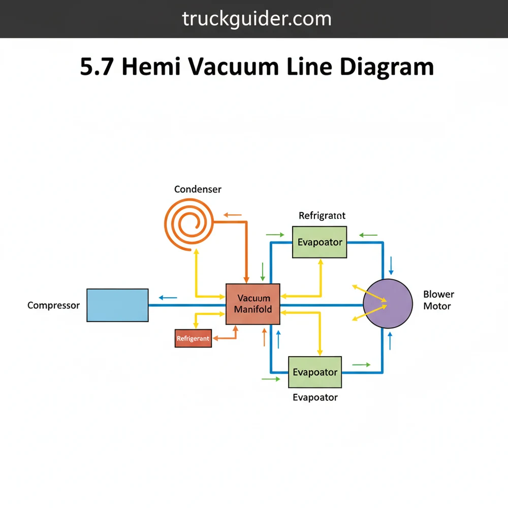
The 5.7 Hemi vacuum line diagram shows the routing from the intake manifold to the HVAC actuators and vacuum reservoir. This system uses engine vacuum to control air doors, ensuring air travels past the evaporator or heater core. Proper connections are vital for the blower motor to direct air correctly through vents.
📌 Key Takeaways
- Provides a roadmap for diagnosing HVAC door actuator failures
- The intake manifold is the primary vacuum source for the system
- Inspect lines for cracks or brittleness to prevent airflow issues
- Use a vacuum pump to test individual actuators for leaks
- Refer to this diagram when air only blows through defrost vents
Understanding your vehicle’s 5.7 Hemi vacuum line diagram is essential for ensuring both optimal engine performance and a comfortable cabin environment. Whether you are dealing with a rough idle or an HVAC system that refuses to switch between floor and defrost modes, a clear map of these connections is your most valuable tool. This article provides a comprehensive breakdown of the vacuum and refrigerant systems associated with the 5.7 Hemi, explaining how components like the compressor and evaporator work in tandem with vacuum-actuated doors. You will learn how to identify each line, troubleshoot leaks, and maintain your system for long-term reliability. By the end of this guide, you will be able to navigate the complex web of hoses and components that define the 5.7 Hemi vacuum line diagram with total confidence.
Understanding the 5.7 Hemi Vacuum and HVAC Diagram Layout
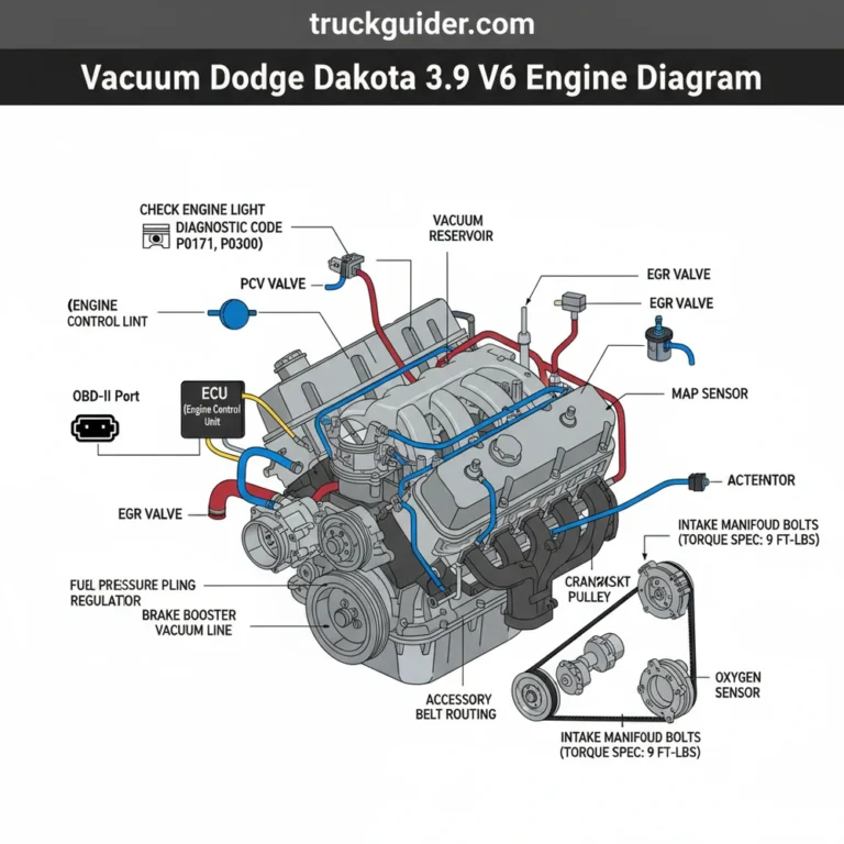
The 5.7 Hemi engine utilizes a sophisticated network of vacuum lines that serve two primary functions: managing engine emissions and controlling the internal climate control doors within the cabin’s air handler. When looking at a 5.7 Hemi vacuum line diagram, the first thing you will notice is the source of the vacuum. The intake manifold acts as the primary vacuum reservoir during engine operation. From here, lines branch out to various critical components, including the brake booster, the PCV (Positive Crankcase Ventilation) system, and the HVAC vacuum storage tank.
The diagram typically utilizes color-coding to help technicians and DIY enthusiasts distinguish between different circuits. For instance, a black line often denotes the main supply line from the intake manifold, while a red or blue line might indicate the vacuum signal sent to the heater control valve or the internal blend doors. In the context of the HVAC system, the vacuum lines are responsible for moving the physical doors inside the air handler. These doors determine whether air passes through the heat exchanger (heater core) for warmth or the evaporator for cooling.
Another critical aspect of the diagram involves the refrigerant cycle. While vacuum lines move the mechanical parts, the refrigerant lines move the thermal energy. The diagram will show the flow from the compressor, which pumps high-pressure gas to the condenser located at the front of the vehicle. From there, the refrigerant travels through an expansion valve into the evaporator located inside the dash. Understanding how these two systems—the vacuum control and the refrigerant flow—interact is the key to mastering the 5.7 Hemi vacuum line diagram.
On many 5.7 Hemi configurations, the vacuum reservoir is hidden inside the passenger side fender well or integrated into the cowl. If your HVAC vents only blow through the defrost setting regardless of your selection, a cracked line leading to this reservoir is the most likely culprit.
Deep Dive: Component Identification and Function

To effectively use a 5.7 Hemi vacuum line diagram, you must be able to identify the physical components under the hood and behind the dashboard. Each part plays a specific role in either engine stability or passenger comfort.
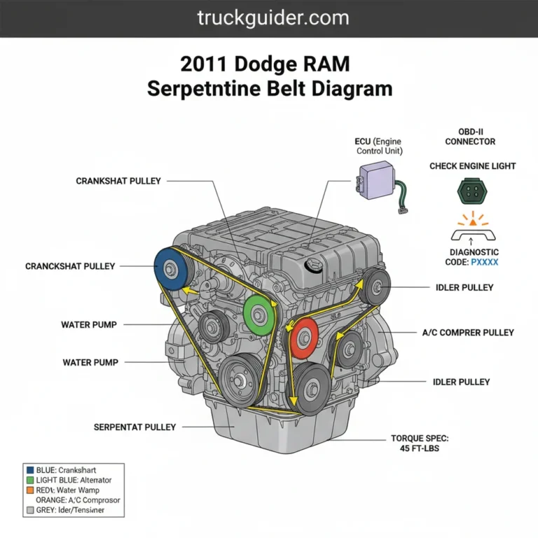
The compressor is the heart of the cooling system. Driven by the engine’s serpentine belt, it compresses the refrigerant gas, raising its temperature and pressure. On a 5.7 Hemi, the compressor is typically located on the lower side of the engine block. If the vacuum signal to the HVAC controls is lost, the compressor might still run, but the air handler won’t be able to direct the cold air to your face.
The condenser is a large, grid-like structure situated in front of the radiator. Its job is to dissipate the heat absorbed from the cabin. As the high-pressure gas flows through the condenser, it cools down and turns into a high-pressure liquid. This is where the “heat exchange” process begins in earnest, moving thermal energy from the vehicle to the outside air.
Inside the cabin, the evaporator acts as the counterpart to the condenser. The high-pressure liquid refrigerant expands and cools rapidly as it enters the evaporator. The blower motor then pushes air across the cold fins of the evaporator. This chilled air is then directed through the air handler to the various vents. If your 5.7 Hemi vacuum line diagram shows a leak in the “recirculation door” circuit, the blower motor may struggle to pull air from the return duct, leading to poor cooling performance in high-humidity environments.
The heat exchanger, often referred to as the heater core, is responsible for cabin warmth. It uses engine coolant to provide heat. Vacuum-actuated valves often control the flow of hot coolant into this exchanger. If the vacuum line to this valve is damaged, you may find yourself with a heater that is stuck “on” even during the peak of summer.
Step-by-Step Guide: Interpreting and Repairing Vacuum Lines
📤 Share
💾 Download
Interpreting a complex diagram can be daunting, but following a structured approach makes the task manageable. Use the following steps to trace and repair lines based on your 5.7 Hemi vacuum line diagram.
- 1. Locate the Primary Vacuum Source: Start at the intake manifold. Identify the thickest vacuum hose; this is the main supply line. Ensure the connection is tight and the rubber hasn’t become brittle or “spongy” due to oil exposure.
- 2. Inspect the Check Valve: Most 5.7 Hemi systems use a small plastic check valve between the manifold and the HVAC system. This valve maintains vacuum in the reservoir even when the engine is under heavy load (low vacuum). Test it by blowing into it; air should only flow in one direction.
- 3. Trace the Line to the Firewall: Follow the line as it passes through the firewall into the cabin. This is a common point for chafing. The diagram will show this line entering the back of the HVAC control head or the vacuum manifold inside the dash.
- 4. Identify the Air Handler Actuators: Once inside, the vacuum is distributed to various actuators on the air handler. These look like small metal or plastic canisters with a rod attached. Using a hand-held vacuum pump, apply vacuum to each actuator to see if it moves the corresponding door (e.g., the defrost door or the floor door).
- 5. Verify the Return Duct and Recirculation Logic: Locate the recirculation door. According to the diagram, this should close when the “Max AC” setting is selected, pulling air through the return duct rather than from outside. If the vacuum line is disconnected, the door will default to the “outside air” position.
- 6. Check the Compressor Engagement: While not strictly vacuum-operated on modern Hemi engines, the compressor engagement is often tied to the HVAC control unit. Ensure the electrical connector to the compressor clutch is secure and that the refrigerant levels are sufficient to trigger the low-pressure switch.
- 7. Replace Damaged Sections: If a leak is found, cut out the damaged section and use a plastic barbed union to join a new piece of vacuum-rated hose. Avoid using standard rubber fuel line, as it can collapse under high vacuum.
- 8. Final System Test: Start the engine and cycle through all HVAC modes. Listen for the faint “hiss” of vacuum switching. If the air redirects correctly to all vents, your repair is successful.
Never attempt to service the refrigerant lines (compressor to condenser/evaporator) without proper recovery equipment. Refrigerant is under high pressure and can cause instant frostbite and environmental damage if released improperly.
Common Issues & Troubleshooting with the 5.7 Hemi Vacuum System
Vacuum leaks are the most frequent problem owners encounter when dealing with the 5.7 Hemi. A leak doesn’t just affect your AC; it can cause a “lean” condition in the engine, leading to a check engine light (often codes P0171 or P0174) and a rough idle.
One of the most telling signs of a vacuum issue is the “Default to Defrost” symptom. Safety regulations require that if the HVAC system loses vacuum control, the default position of the air handler doors must be the windshield defrost setting. This ensures the driver can always see out of the car. If your AC is blowing cold but only out of the top of the dash, you have a vacuum supply issue, not a refrigerant issue.
Another common problem involves the blower motor. While the blower motor is electrical, its efficiency depends on the air handler being clear of debris. If the return duct is blocked or the cabin air filter is clogged, the blower motor will strain, leading to premature failure or blown resistors. The diagram helps you locate these components so you can ensure the path for airflow is unobstructed.
If you notice a hissing sound behind the glovebox or the center console, this usually indicates a failed vacuum actuator or a disconnected line at the HVAC controller. You can use the 5.7 Hemi vacuum line diagram to pinpoint which color-coded line is responsible for the specific vent that isn’t working.
To find a stubborn vacuum leak under the hood, use a small unlit propane torch. With the engine idling, move the torch head (unlit!) along the vacuum lines. If the engine RPM rises slightly, you’ve found the spot where the engine is sucking in the propane, indicating a hole in the line.
Maintenance Tips and Best Practices
Maintaining the vacuum and HVAC systems on a 5.7 Hemi requires a proactive approach. Regular inspections can prevent minor issues from turning into expensive repairs.
- ✓ Inspect Rubber Components Yearly: The heat generated by the 5.7 Hemi is significant. This heat causes rubber vacuum lines to dry out and crack. Check the lines near the back of the engine and near the heat exchanger especially closely.
- ✓ Keep the Condenser Clean: Use a low-pressure garden hose to spray out bugs and dirt from the condenser fins. A clean condenser allows for better heat exchange, which reduces the workload on the compressor.
- ✓ Replace Cabin Air Filters: A clogged filter restricts airflow to the evaporator and blower motor. This can lead to ice buildup on the evaporator, which eventually blocks all airflow.
- ✓ Lubricate Actuator Linkages: Occasionally, the plastic doors inside the air handler can become “sticky.” A small amount of silicone-based lubricant on the visible linkages can help the vacuum actuators move the doors smoothly.
When replacing components, always opt for high-quality, OEM-spec parts. The vacuum actuators and the blower motor are often buried deep within the dashboard. Using a cheap, off-brand component might save you thirty dollars today, but if it fails in six months, you will spend hours of labor (or hundreds in mechanic fees) to replace it again.
Quality refrigerant is also a factor. Ensure that any service to the AC system uses the correct weight and type of refrigerant as specified on the under-hood sticker. Overcharging the system can damage the compressor valves, while undercharging prevents the evaporator from reaching the necessary temperature to cool the cabin effectively.
The Role of the Vacuum Reservoir in System Stability
One often overlooked component in the 5.7 Hemi vacuum line diagram is the vacuum reservoir. Because the engine does not produce a consistent level of vacuum at all times (vacuum drops significantly during wide-open throttle acceleration), a reservoir is needed to act as a “battery” for vacuum.
This reservoir allows the HVAC system to maintain its position even when you are merging onto a highway or towing a heavy load. If you find that your AC vents switch to defrost every time you accelerate hard, the check valve or the reservoir itself has failed. The reservoir is often a black plastic box or a spherical tank located in a corner of the engine bay. Checking the integrity of this component is a vital part of any comprehensive troubleshooting strategy.
By mastering the 5.7 Hemi vacuum line diagram, you gain a deeper understanding of how your vehicle operates. From the moment the compressor kicks in to the moment the air handler directs chilled air through the vents, every step is a coordinated dance of physics and engineering. Whether you are performing a simple hose replacement or a full-scale HVAC overhaul, the knowledge of how vacuum and refrigerant systems interact will ensure your Hemi stays cool and powerful for years to come. Remember to always work safely, use the right tools, and refer back to your diagram whenever you encounter a connection that doesn’t look quite right. High-performance engines like the 5.7 Hemi deserve high-performance maintenance.
Frequently Asked Questions
Where is the HVAC vacuum reservoir located?
On most 5.7 Hemi vehicles, the HVAC vacuum reservoir is located behind the passenger side fender liner or tucked under the dashboard near the firewall. It stores vacuum to maintain consistent door operation during acceleration. Locate it by following the thin black plastic line from the intake manifold check valve.
What does the 5.7 hemi vacuum line diagram show?
The 5.7 hemi vacuum line diagram displays the intricate network of tubes connecting the engine intake to the climate control system. It highlights how vacuum signals trigger the blend and mode doors. This allows the system to manage airflow produced by the blower motor across the internal cooling components.
How many vacuum connections does the HVAC controller have?
The main HVAC control head typically features four to six vacuum connections, depending on the specific model year and trim. These ports connect to various color-coded vacuum lines that lead to specific actuators, such as the defrost, floor, and recirculate doors, ensuring precise control of the cabin climate.
What are the symptoms of a bad vacuum line?
Symptoms of a leaking vacuum line include the HVAC system defaulting to the defrost vents regardless of settings. You might also notice a hissing sound under the dashboard or poor performance from the AC compressor if the control signals are lost. Inspecting the lines for cracks or heat damage is essential.
Can I replace HVAC vacuum lines myself?
Most DIY enthusiasts can replace these vacuum lines using basic hand tools and bulk vacuum tubing from an auto parts store. The task involves tracing the lines using the 5.7 hemi vacuum line diagram and swapping out old, brittle sections. Ensure all connections to the reservoir are airtight.
What tools do I need for vacuum testing?
To diagnose the vacuum system, you will need a handheld vacuum pump with a gauge, a set of needle-nose pliers, and a flashlight. These tools allow you to test individual actuators and verify that the system maintains pressure, ensuring that the condenser and evaporator can function within their cycles.

![How To Fix P0562 Code [2026]](https://truckguider.com/wp-content/uploads/2026/03/featured-9495f858.webp)