6.7 Cummins Engine Parts Diagram: Detailed Component Identification and Technical Layout
For diesel enthusiasts and professional mechanics alike, the 6.7 Cummins stands as the gold standard of heavy-duty power, delivering over 1,000 lb-ft of torque in its latest iterations. However, with its sophisticated emissions systems and high-pressure fuel delivery, identifying specific components for maintenance or repair requires more than just a passing glance under the hood. Navigating the complex architecture of this inline-6 powerhouse is essential for ensuring longevity and peak performance. This technical guide provides a detailed 6.7 Cummins engine parts diagram breakdown, offering an expert look at the architecture, internal assembly, and peripheral systems that make this engine a reliable legend.
Understanding the 6.7 Cummins Engine Architecture and Core Block Assembly
The 6.7L Cummins Turbo Diesel represents a significant leap in engineering from its 5.9L predecessor. Introduced in mid-2007 to comply with stricter EPA Tier 2 Bin 5 emission standards, the engine was not merely a bored-out version of the older block. The most critical advancement in its structural 6.7 Cummins engine parts diagram is the utilization of Compacted Graphite Iron (CGI) for the engine block construction. Unlike traditional grey iron, CGI offers a molecular structure that provides significantly higher strength-to-weight ratios. According to the blank”>official guide, this material choice allows the engine to withstand much higher cylinder pressures while actually reducing the overall mass of the casting.
By The Numbers
Higher Tensile Strength (CGI)
Increased Stiffness
Engine Firing Order
Cylinder Head and Thermal Management
The cylinder head features a 24-valve configuration (four valves per cylinder) which facilitates superior air-to-fuel mixing and exhaust scavenging. A key technical detail in the layout is the integration of the intake manifold into the head casting, which minimizes potential leak points but requires specialized gaskets during a rebuild. Thermal management is handled by a sophisticated cooling jacket layout designed to eliminate “hot spots” between the cylinders—a common pitfall in high-torque diesel applications. When reviewing a parts diagram, pay close attention to the torque-to-yield (TTY) bolts used for the cylinder head; these are designed for single-use only and must be replaced whenever the head is removed to ensure a proper seal against the high-compression environment.
Rotating Assembly and Internal 6.7 Cummins Engine Parts Diagram Details
The internal reciprocating components of the 6.7 Cummins are built to withstand incredible forces. In modern high-output versions, the engine produces up to 1,075 lb-ft of torque, placing immense stress on the crankshaft and connecting rods. The connecting rods are made from forged steel and utilize a “fracture-split” or “crack-and-cap” manufacturing process. This ensures that the rod cap and the rod body mate perfectly, providing a stronger bearing surface than traditional machined caps.
Forged Strength
Forged steel connecting rods handle cylinder pressures exceeding 2,500 psi without deformation.
Gallery Cooling
Aluminum alloy pistons feature internal cooling galleries where oil is sprayed to dissipate combustion heat.
Synchronization and Valvetrain
The synchronization between the crankshaft and the camshaft is achieved through a robust gear-driven timing set located at the front of the engine block. This design is preferred in professional applications over belts or chains because it eliminates the risk of timing jumps during rapid RPM changes. The valvetrain uses pushrods and rocker arms, with later models transitioning to hydraulic lifters to reduce maintenance needs. A critical component often overlooked in basic diagrams is the vibration damper (harmonic balancer) on the front of the crankshaft. Over 15 years of experience has shown that a worn damper is a leading cause of crankshaft failure, as it can no longer absorb the torsional stresses generated by the long stroke of the inline-6.
High-Pressure Fuel System Components and Injection Mapping
The fuel system is the most technically complex part of the 6.7 Cummins diagram. High-pressure common rail (HPCR) technology allows for pressures reaching 36,000 psi. This pressure is generated by the high-pressure fuel pump, which has seen significant revisions. Between 2019 and 2020, the engine utilized the Bosch CP4.2 pump, which became a point of concern for many owners due to sensitivity to fuel lubrication. Starting in 2021, Ram returned to the proven Bosch CP3 pump design. Identifying which pump your engine has is vital when sourcing
At 36,000 psi, even microscopic particles act like sandpaper inside your fuel injectors. Always use multi-stage filtration and replace the Water-in-Fuel (WIF) sensor immediately if it shows signs of corrosion. A fuel system failure often requires replacing the entire common rail, injectors, and lines to prevent cross-contamination.
Air Handling, Turbocharger, and Emissions Control Systems
The 6.7 Cummins breathes through a Holset Variable Geometry Turbocharger (VGT). Unlike a standard turbo, the VGT uses a sliding nozzle ring to vary the exhaust gas flow across the turbine wheel. This allows the turbo to provide instantaneous boost at low RPMs while also acting as an exhaust brake. In fact, the VGT can provide up to 250 braking horsepower, which is essential for safely towing heavy loads on steep descents as detailed in Ram specs.
Emissions Layout: EGR, DPF, and SCR
The emissions control system is a major component of any 6.7 Cummins engine parts diagram. It consists of three primary stages:
- Exhaust Gas Recirculation (EGR): Diverts cooled exhaust gases back into the intake to lower combustion temperatures and reduce NOx.
- Diesel Particulate Filter (DPF): Captures soot particles. Over time, these are burned off during a “regeneration” cycle.
- Selective Catalytic Reduction (SCR): Introduced in 2013 for Ram 2500/3500 models, this system injects Diesel Exhaust Fluid (DEF) into the exhaust stream to further neutralize NOx.
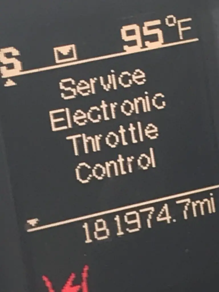
Expert Tip: The VGT actuator is a frequent failure point due to soot buildup. Regularly using the exhaust brake function helps keep the sliding nozzle ring in motion, preventing it from sticking and triggering a limp mode or “Service Exhaust System” message.
Utilizing Technical Diagrams for Professional Maintenance and Repair
When working with a 6.7 Cummins engine parts diagram, the most important piece of information you can have is the Engine Serial Number (ESN). Because there are over 20 different variations of this engine since 2007, a generic diagram may lead you to order the wrong O-ring or gasket. The ESN is typically located on the data plate on the side of the gear housing, just behind the air compressor or power steering pump.
📋
Step-by-Step Guide to Part Identification
Find the 8-digit Engine Serial Number on the rocker cover or the gear housing data plate. This ensures you are viewing the correct sub-diagram for your build year.
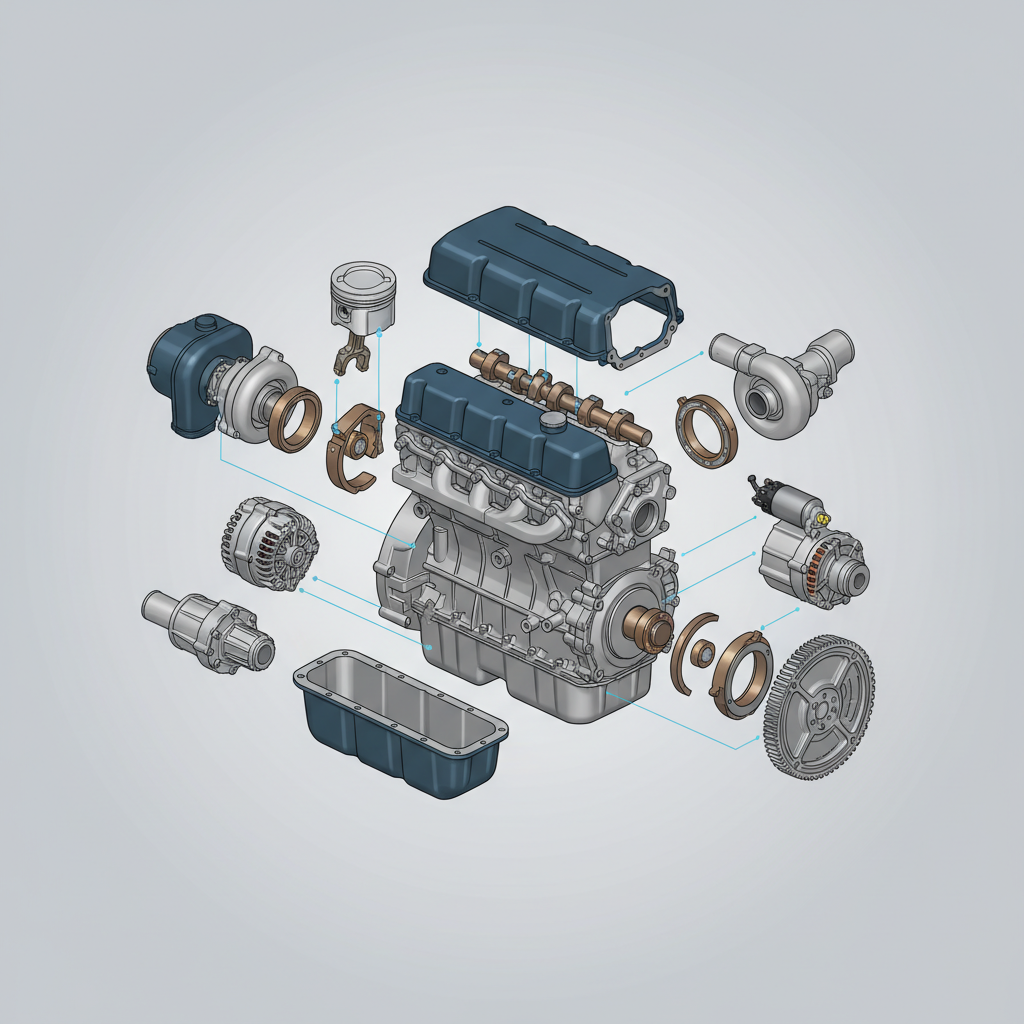
Use an exploded view diagram to see the relationship between components. This is crucial for identifying hidden gaskets and the specific order of washers and fasteners.
Always use a calibrated torque wrench. For example, the valve cover bolts on a 6.7 Cummins require a specific sequence and a relatively low torque (approx. 18 lb-ft). Over-tightening can easily crack the composite cover or strip the aluminum threads in the head.
In summary, the 6.7 Cummins is a masterclass in diesel engineering, combining the strength of a CGI block with the precision of high-pressure common rail injection and variable geometry turbocharging. Understanding the evolution of these parts—from the transition away from the CP4 pump to the complexities of the SCR system—is what separates a casual owner from a professional diesel technician. By utilizing ESN-specific diagrams and sticking to a rigorous maintenance schedule with OEM-quality parts, you can ensure that your Cummins engine remains a reliable workhorse for hundreds of thousands of miles. Consult your specific Engine Serial Number when ordering replacement parts to ensure professional-grade fitment and performance.
Frequently Asked Questions
Where can I find a reliable parts diagram for my specific 6.7 Cummins?
The most reliable source for a 6.7 Cummins engine parts diagram is the Cummins QuickServe online portal. By entering your unique Engine Serial Number (ESN), you can access exploded views and genuine part numbers tailored to your specific engine build and year model, ensuring professional accuracy.
What are the most common problems with the 6.7 Cummins engine?
Common issues often involve the emissions system, specifically EGR cooler clogging and DPF soot accumulation. Additionally, 2019-2020 models faced concerns regarding the CP4 high-pressure fuel pump, leading to a massive recall and a return to the more reliable CP3 pump design in subsequent years.
How do I identify the difference between a CP3 and CP4 fuel pump?
Visual identification is the most expert method. The Bosch CP3 pump used in older and newer models is larger with three high-pressure pumping elements. The CP4.2 pump, found on 2019-2020 models, is more compact, has two heads, and features a distinct vertical mounting flange.
What is the firing order of the 6.7 Cummins engine?
As an inline-6 diesel engine, the 6.7 Cummins follows the standard firing order of 1-5-3-6-2-4. This sequence is critical for timing the fuel injection events and ensuring smooth engine operation and balanced torsional forces across the crankshaft.
What are the torque specifications for the head bolts on a 6.7 Cummins?
For most 6.7 Cummins models, the head bolt torque sequence involves multiple steps: an initial 70 ft-lbs, followed by 105 ft-lbs, and a final 90-degree turn. However, because these are torque-to-yield bolts, professional technicians recommend referring to the specific service manual for your ESN to confirm exact specs.