6.7 Cummins Fan Clutch Wiring Diagram And Electrical Troubleshooting Guide
When your 6.7 Cummins is pulling a heavy grade in mid-July, the only thing standing between your engine and a catastrophic overheat is the electronically controlled viscous fan clutch. Unlike the simpler mechanical clutches of the past, this system relies on a complex interplay of Pulse Width Modulation (PWM) signals, sensor feedback, and precise voltage references. Electrical failures in the fan clutch system can lead to erratic cooling, reduced fuel economy, or a truck that sounds like a jet engine even when idling—leaving many owners frustrated by complex wiring diagrams and cryptic trouble codes. In this complete guide, we will provide a clear 6.7 Cummins fan clutch wiring diagram, break down the pinout specifications, and walk you through professional diagnostic steps to identify whether your issue is the clutch itself or a broken wire in the harness.
Understanding the 6.7 Cummins Electronically Controlled Viscous Fan Clutch
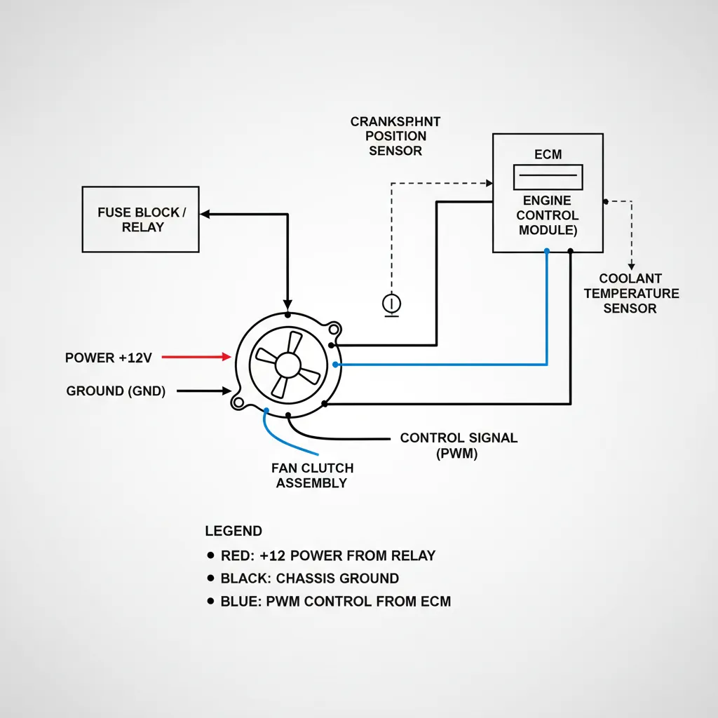
The transition from the 5.9L Cummins to the 6.7L platform brought about a comprehensive shift in cooling strategy. While older engines used a purely thermal bimetal spring to engage the fan, the 6.7 Cummins utilizes an electronically controlled viscous fan clutch. This system allows the Engine Control Module (ECM) to command a specific fan speed regardless of the current engine RPM, providing reliable cooling only when necessary. This precision is achieved through Pulse Width Modulation (PWM).
The ECM monitors a suite of parameters—including coolant temperature, intake air temperature (IAT), AC high-side pressure, and transmission oil temperature—to determine the required “duty cycle.” Inside the clutch, an internal solenoid receives this PWM signal and opens a valve to allow viscous fluid to flow into the working chamber. As fluid fills the chamber, the shear force increases, causing the fan blades to lock closer to the water pump speed. To ensure the system is working correctly, a Hall Effect speed sensor inside the clutch provides real-time RPM feedback to the ECM. If the actual fan speed does not match the commanded speed, the ECM will trigger a fault code.
Unlike mechanical clutches that fail “off,” these electronic units are designed with a mechanical failsafe. If the electrical signal is lost completely, the internal valve defaults to a position that allows partial or full engagement to prevent an immediate meltdown, though this results in a permanent “jet engine” sound and poor fuel economy.
Interpreting the 6.7 Cummins Fan Clutch Wiring Diagram by Pinout
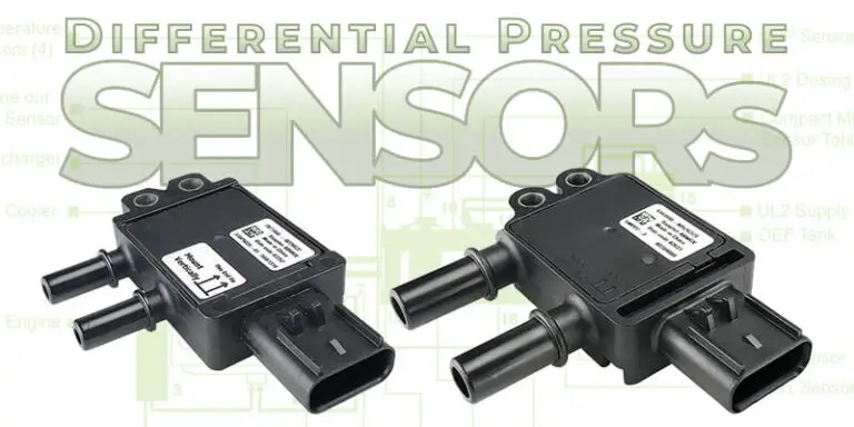
To diagnose a fan clutch issue effectively, you must understand the 6-pin weather-pack connector located on the fan shroud. While wire colors can vary slightly between a 2008 Ram 2500 and a 2018 Ram 3500, the pinout configuration remains largely consistent for the 6.7 Cummins engine. Referencing a trusted guide for your specific VIN is always recommended, but the following pinout is the industry standard for most 6.7L applications.
A common pitfall in the field involves technicians misidentifying the 5V reference (Pin 2) as a 12V power source. Applying 12V directly to Pin 2 during testing will instantly destroy the internal Hall Effect sensor, necessitating a professional replacement of the entire clutch assembly. Always use a digital multimeter to verify your source voltages before performing jumper tests.
Common Fan Clutch Wiring Problems and Physical Inspection
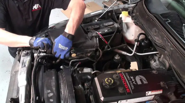
Before diving into complex electrical testing, a quality physical audit of the harness is mandatory. Research indicates that faulty wiring accounts for approximately 30% of ‘bad fan clutch’ misdiagnoses in professional repair shops. On the 6.7 Cummins, the wiring harness is subjected to extreme heat cycles and constant vibration.
The primary “chaffing” point is where the harness exits the fan shroud and transitions to the main engine block. If the plastic clips holding the harness in place have become brittle and broken, the harness can vibrate against the sharp edge of the radiator shroud or even make contact with the harmonic balancer. This often leads to a “hidden break”—a scenario where the wire’s insulation looks perfectly intact, but the copper core inside has fractured due to work-hardening. Furthermore, moisture intrusion into the 6-pin connector can cause pins to corrode or “push out,” leading to intermittent communication failures with the ECM.
Fan clutch failure is a common issue in high-mileage 6.7 Cummins engines, often occurring after 100,000 miles. At this stage, the wire insulation becomes brittle. Avoid tugging on the harness during other repairs, as this can easily cause an internal short.
Step-by-Step Multimeter Testing for Fan Clutch Circuits
To accurately diagnose the system, follow this comprehensive testing procedure using a high-quality digital multimeter. Ensure the vehicle is off but the ignition is in the “Run” position for voltage checks.
📋
Step-by-Step Diagnostic Guide
Disconnect the harness. Set your multimeter to DC Volts. Test Pin 5 against a known good chassis ground. You should see 12V+. If 0V, check the fan clutch fuse in the Power Distribution Center (PDC).
Measure Pin 2. You must see a steady 5.0V signal. If this voltage is erratic or missing, the ECM may have an internal fault or there is a short in another sensor sharing this reference circuit.
Switch to Ohms (Resistance). Test Pin 3 and Pin 6 to the engine block. Resistance should be less than 0.2 Ohms. Research suggests a variance of more than 0.5V on the ground circuit can trigger erratic fan behavior.
For an advanced test, you can back-probe Pin 1 while the connector is plugged in. Manually spin the fan with the key ON. You should see the voltage on your multimeter pulse between 0V and 5V as the Hall Effect sensor passes the internal magnets. If the voltage stays at a flat 5V or 0V while spinning, the internal speed sensor is dead.
Diagnosing Fan Clutch Issues Using Diagnostic Trouble Codes (DTCs)
The ECM is highly sensitive to the fan clutch circuit. When a fault is detected, it will often store a specific DTC and may put the truck into a “limp mode” or derated state to prevent engine damage. Using a scan tool is the fastest way to narrow down the search area.
P0480: Fan Control Circuit
Indicates an open or short in the PWM control circuit (Pin 4). This is usually a wiring issue between the ECM and the clutch.
P0483: Fan Speed Performance
The ECM commanded a speed, but the sensor feedback (Pin 1) shows the fan is spinning too slow or too fast. Possible mechanical slip.
P0528: Fan Speed No Signal
The ECM sees 0 RPM feedback. This is commonly caused by a broken speed sensor wire or a failed Hall Effect sensor inside the clutch.
An expert tip for troubleshooting is to perform a “Fan Clutch Actuation Test” using a bi-directional scan tool. By forcing the fan to 100% duty cycle while the engine is running, you can immediately hear if the clutch is engaging. If it engages during the test but not during normal driving, your problem is likely a sensor input (like a faulty AC pressure sensor) rather than the fan clutch itself.
Industry Data: Cooling System Reliability
6.7 Overheating Related to Clutch
Average Miles at Failure
Professional Replacement Procedure and Preventative Maintenance
Replacing the fan clutch on a 6.7 Cummins requires trusted tools and patience. Because the fan clutch nut is attached to the water pump shaft, you will need a specialized thin-profile fan clutch wrench and a holding tool. The thread is typically right-hand (standard), but check your specific model year as some early 6.7L transitions varied. Torque specifications are critical; most manuals call for 90-100 lb-ft to ensure the unit does not spin off during rapid deceleration.
The most critical step in the replacement process is the harness routing. Ensure the new wiring is secured in all factory clips. A common DIY mistake is leaving the harness with too much slack, allowing the fan blades to chop through the wires within the first 50 miles of operation. Before plugging in the new unit, use electrical contact cleaner to remove any oil or debris from the connector to ensure a reliable signal path. For those who frequently tow heavy loads in extreme heat, consider an aftermarket fan clutch controller which allows you to manually override the ECM and lock the fan at 100% before you hit a steep grade.
Every 30,000 miles, inspect the fan clutch harness for signs of rubbing. Applying a small amount of dielectric grease to the connector pins can prevent the corrosion issues common in the “Salt Belt” regions, extending the life of your cooling system significantly.
For more expert tips and community-driven troubleshooting, visit dodgecumminsforum.com to see how other owners have solved persistent cooling issues.
Conclusion
The 6.7 Cummins uses a sophisticated PWM-controlled fan clutch that requires precise 5V and 12V signals to operate. Most fan clutch failures are actually wiring harness issues caused by chaffing against the radiator shroud or corrosion in the 6-pin connector. Utilizing a multimeter to verify power, ground, and signal is the only reliable way to confirm a failed component before spending money on replacements. If your diagnostics confirm a failed unit, ensure you replace it with a high-quality OEM or trusted heavy-duty aftermarket clutch to maintain cooling reliability during your next haul. Staying proactive with your cooling system ensures your Cummins remains the reliable workhorse it was built to be.
Frequently Asked Questions
Where can I find a 6.7 Cummins fan clutch wiring diagram?
A detailed 6.7 Cummins fan clutch wiring diagram can be found in the factory service manual for your specific model year. Generally, it consists of a 6-pin connector featuring a 12V fused power supply, a 5V reference from the ECM, a signal return, a ground, and the PWM control wire. Always verify wire colors against your specific VIN.
How do I test the fan clutch wiring with a multimeter?
To test the wiring, set your multimeter to DC volts. With the key on, check for 12V at the power pin and 5V at the reference pin. Check for continuity to ground on the ground pin. If these are present, use a scan tool to command fan engagement while checking for a fluctuating PWM signal on the control wire.
What are the symptoms of a bad fan clutch on a 6.7 Cummins?
Common symptoms include the engine overheating while idling or towing, the fan staying engaged at all times (creating excessive noise and drag), or the ‘Check Engine’ light illuminating with codes like P0480 or P0483. You may also notice a significant drop in AC performance when the vehicle is stationary.
Can I drive my 6.7 Cummins with a failed fan clutch?
Driving with a failed fan clutch is not recommended, especially when towing or in stop-and-go traffic. While the vehicle may stay cool at highway speeds due to natural airflow, the lack of active cooling at low speeds can lead to rapid overheating, which risks head gasket failure and engine warping.
How do I replace the fan clutch on a Dodge Ram 6.7 Cummins?
Replacement involves removing the cooling fan shroud bolts, using a large fan clutch wrench to turn the nut clockwise (it is typically right-hand thread on the 6.7), and disconnecting the 6-pin electrical harness. Care must be taken to secure the new harness back into the factory clips to prevent it from being severed by the fan blades.