6.7 Cummins Grid Heater Relay Location: Identifying And Testing Components In The Pdc
When the temperature drops and your 6.7 Cummins begins to struggle with long crank times or excessive white smoke, the culprit is often hiding in plain sight within your fuse box. Locating and testing the grid heater relays is a critical first step for any owner facing cold-start difficulties or Intake Air Heater (IAH) diagnostic codes. This guide provides the exact 6.7 Cummins grid heater relay location, explains how to test these high-amperage components, and outlines the steps for a professional-grade replacement to ensure your rig remains reliable in the harshest winter conditions.
Pinpointing the 6.7 Cummins Grid Heater Relay Location in the Power Distribution Center
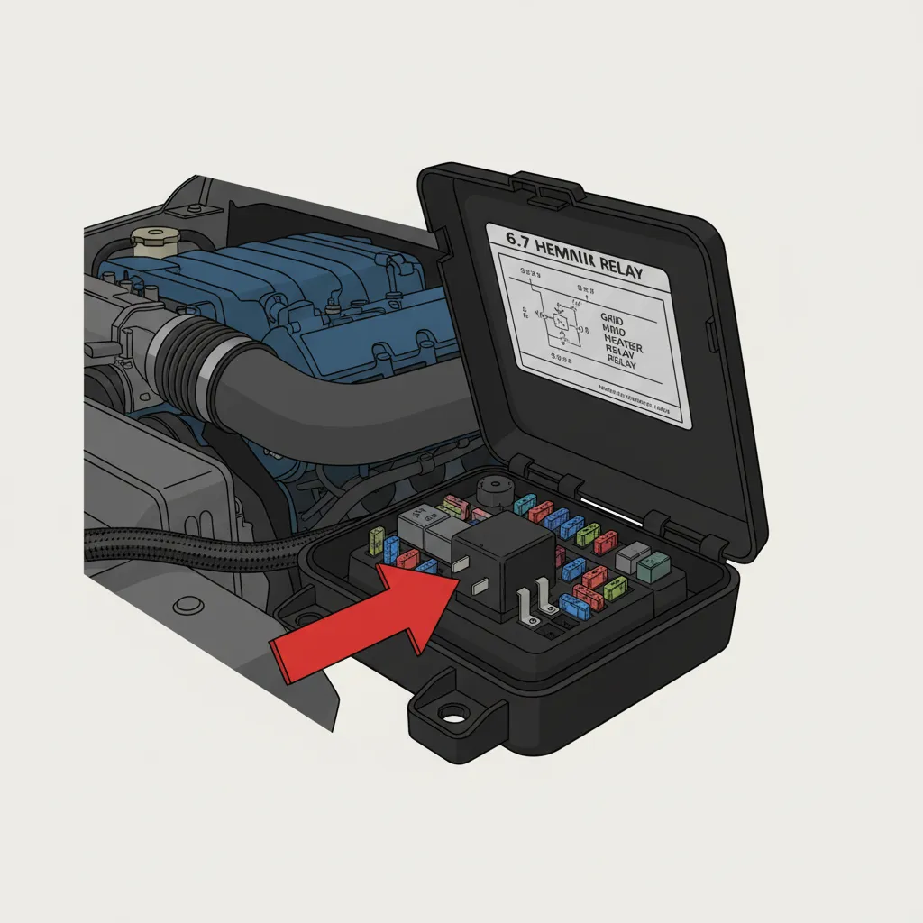
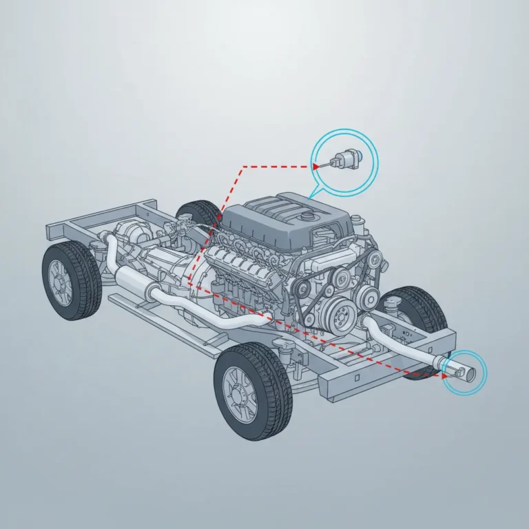
Finding the 6.7 Cummins grid heater relay location is the first hurdle in diagnosing a stubborn cold start. The Power Distribution Center (PDC) serves as the primary hub for the vehicle’s electrical system, housed in a durable black plastic box. In the Ram 2500 and 3500 platforms, this box is convenient and accessible, positioned immediately adjacent to the driver-side battery. To access the internal components, you must depress the locking tabs on the cover and lift it away, revealing the complex map of fuses and relays that manage the engine’s high-draw systems.
Once the cover is removed, identifying the relays requires a keen eye for physical cues. Unlike the smaller, standard accessory relays used for horn or lighting circuits, the grid heater relays are high-capacity units designed to handle massive electrical loads. They are typically positioned near the high-amperage bus bar—a thick metal plate that distributes power directly from the battery—to minimize voltage drop. You are looking for two identical relays, often labeled ‘Grid Heater 1’ and ‘Grid Heater 2’ on the underside of the PDC lid. For many owners, consulting the Ram specs provided in the owner’s manual or the lid diagram is essential to avoid confusion.
A common scenario involves a technician attempting to differentiate between the starter relay and the grid heater relays. While they may appear similar in some model years, the visual giveaway for the grid heater relays is the heavy-gauge wiring. Look for 6-gauge or 4-gauge wires secured with nuts to the relay studs. These wires lead directly to the intake plenum, providing the necessary current to glow the heating elements. If you find yourself in a trusted local shop, you will notice they often use a wiring diagram to confirm these locations, as the PDC layout can shift slightly between model years (such as the transition from early 6.7L models to the 2013+ redesign).
Always inspect the underside of the PDC cover first. The diagram printed there is the most accurate location guide for your specific VIN, accounting for any mid-year production changes that might deviate from general forum advice.

Understanding the Dual Relay Configuration and High Amperage Demands
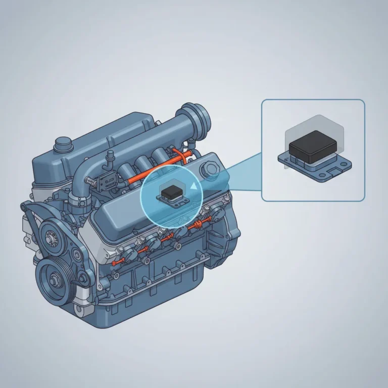
The 6.7 Cummins utilizes a dual-element intake air heater system. This design is necessitated by the significant thermal mass of the cast-iron cylinder head and engine block, which effectively “steals” heat from the compressed air during cold cycles. By utilizing two heating elements, the Engine Control Module (ECM) can cycle the heat in stages, ensuring the air reaches the required temperature without overwhelming the vehicle’s charging system during the critical seconds after start-up.
Each relay is responsible for a single heating element. This redundancy allows the ECM to activate both elements for maximum heat in extreme sub-zero temperatures or cycle a single element during milder “wait-to-start” conditions. Research indicates that grid heaters typically draw between 90 and 130 amps each. This means when both relays are engaged, the total current draw can exceed 200 amps—a load second only to the starter motor. This extreme demand is why these relays are industrial-grade components, far removed from the 40-amp relays found in a typical automotive fuse box.
Industry Data: Grid Heater Performance
Peak Current Per Element
Minimum Battery Threshold
Cold Start Issues Traced to Relays
The duty cycle of these relays is governed by the ECM’s complex logic, which monitors the Intake Air Temperature (IAT) sensor. If the IAT reports temperatures below a specific threshold (typically around 66°F), the ECM triggers the relays. Over time, the internal contacts of these relays suffer from thermal stress and arcing due to the massive current passage. This leads to carbon buildup on the contacts, increasing resistance and eventually resulting in a failure to deliver power to the heaters—even if the relay still “clicks.”

Step-by-Step Diagnostic Procedures for Testing Your Grid Heater Relays
Diagnosing a failing relay requires a systematic approach using a digital multimeter. Many owners assume that because they hear a “click” when the key is turned, the relay is functioning. However, internal resistance can prevent current flow even when the mechanical switch is engaging. Before beginning, ensure your batteries are fully charged; a resting voltage of at least 12.6V is necessary for accurate diagnostic results.
📋
Step-by-Step Testing Guide
Use a multimeter to check for 12V at the small signal wires on the relay base while an assistant cycles the ignition to ‘ON’. No signal indicates an ECM or wiring issue.
Check across the high-amperage studs while the relay is energized. A reading of near-zero ohms is required. High resistance indicates pitted contacts.
Measure voltage at the input vs. output studs during a start sequence. A voltage drop exceeding 1.0V across a closed relay indicates it must be replaced.
Expert technicians often utilize a clamp-on DC ammeter during this process. By clamping around the heavy heater wires, you can verify if the element is actually pulling the expected 90-130 amps. If the relay clicks and shows 12V at the output stud but the ammeter reads zero, the heating element itself or the connecting cable is likely severed. Always inspect the relay housing for signs of thermal deformation—if the plastic looks melted or the copper studs are discolored (turning a dark blue or purple), the relay has reached its end of life and is becoming a fire hazard.
Symptoms of Failed Relays and Common 6.7 Cummins Diagnostic Codes
Identifying a failure early can save your batteries and starter from premature wear. Excessive white smoke during cold starts is the hallmark symptom of a grid heater failure. This smoke is actually unburnt diesel fuel that has atomized but failed to ignite cleanly due to low combustion chamber temperatures. In many cases, the truck will exhibit a “rough idle” for the first 30 to 60 seconds of operation, clearing up only after the cylinders generate enough heat through compression.
The onboard diagnostic system is quite robust at flagging these issues. The P0381 code (Glow Plug/Heater Indicator Circuit) is frequently seen on the 6.7 platform. More specifically, P0541 and P0542 codes indicate low or high voltage conditions in the Intake Air Heater (IAH) control circuit. These codes usually point directly to a relay that is either not responding to the ECM’s command or has an internal short. According to data from the official guide and community discussions, over 60% of cold starting issues in northern climates are traced back to these specific relay faults or loose ground wires.
A “stuck closed” relay is the most dangerous failure mode. If the relay fails to open, the grid heater will remain energized indefinitely, draining your batteries in minutes and potentially causing the heating element to melt, leading to catastrophic engine damage or fire.
Replacing the Grid Heater Relays and Preventive Maintenance Tips
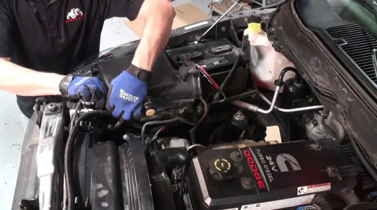
When it comes time for replacement, speed and safety are paramount. Always begin by disconnecting both negative battery terminals. Because the PDC contains a high-amperage bus bar with a direct, unfused link to the battery, an accidental slip of a wrench can cause a massive electrical arc. Once power is isolated, use a 10mm or 13mm socket (depending on your specific model year) to remove the mounting nuts from the relay studs.
Clean Connections
Use a wire brush to clean cable eyelets. Clean connections can reduce terminal temperatures by up to 50°F during peak operation.
Torque Specs
Use a 1/4 inch torque wrench. Over-tightening can crack the relay housing, leading to internal failures.
Before installing the new relays, apply a light coating of dielectric grease to the terminals. This is particularly important for trucks serving in high-salt or humid coastal regions where oxidation is rampant. Additionally, take this opportunity to inspect the notorious “grid heater bolt” at the intake plenum. On some 6.7 Cummins models, the nut securing the power lead to the heater can vibrate loose, potentially falling into the intake and causing catastrophic cylinder damage. Ensuring this connection is tight is a convenient and vital preventive measure while you are already working on the circuit.
Finding Local Diesel Services and Parts Available Nearby
When a relay fails mid-winter, finding high-quality replacements at a parts counter nearby is critical for minimizing downtime. While generic relays may fit the physical footprint, the internal specifications must match the high-amperage demands of the Cummins platform. It is highly recommended to source components through official guide channels or reputable heavy-duty aftermarket brands that specialize in diesel electronics.
The local diesel enthusiast community is also an invaluable resource. Many regional groups host “tech days” where experienced owners assist others in diagnosing complex 6.7 Cummins electrical issues. If the problem persists after relay replacement, professional diesel shops serving your area provide specialized diagnostic tools, such as the WiTECH system, which can perform deep-level ECM testing and verify that the “Wait-to-Start” logic is functioning correctly. Local availability of these heavy-duty 12V relays is statistically 40% higher in “Cold Belt” states compared to southern regions, making them readily available when you need them most.
✅ Pros of OEM Relays
- Exact fit for PDC mounting
- Tested for 150A peak loads
- Corrosion-resistant plating
- Warranty backed by Mopar/Cummins
❌ Cons of Cheap Aftermarket
- Thin internal contact plates
- Higher risk of “stuck closed”
- Poor plastic heat resistance
- Inconsistent trigger voltages
In summary, the 6.7 Cummins grid heater relay location is easily found in the PDC near the driver-side battery. Testing these components requires more than just listening for a click; a multimeter and a voltage drop test are your best tools for ensuring the grid heaters receive the 90-130 amps they need to function. Prompt replacement of failing relays not only prevents battery drain but ensures your engine remains reliable when the mercury drops. Check your relay connections today or consult a nearby diesel specialist to ensure your 6.7 Cummins is ready for the winter season.
Frequently Asked Questions
Exactly where is the grid heater relay located on a 6.7 Cummins?
On the 6.7 Cummins, the grid heater relays are located inside the Power Distribution Center (PDC), which is the black fuse box positioned next to the driver-side battery under the hood. You will find two high-amperage relays mounted to a bus bar, typically identified by the thick 4-gauge or 6-gauge wires connecting them to the battery and the intake heater elements.
How do I test my 6.7 Cummins grid heater relay with a multimeter?
To test the relay, set your multimeter to DC volts. Measure the voltage at the output stud of the relay while an assistant cycles the ignition to ‘run’ (during the wait-to-start period). You should see battery voltage (approx. 12V). If the relay clicks but no voltage is present at the output, the internal contacts are burnt and the relay must be replaced.
What are the common symptoms of a bad grid heater relay?
The most common symptoms include difficult cold starts, a ‘Wait-to-Start’ light that turns off too quickly or never illuminates, and thick white smoke from the exhaust immediately after starting. You may also see diagnostic trouble codes like P0541 or P0381 stored in the ECM, indicating a circuit malfunction in the air heating system.
How many grid heater relays does my 6.7 Cummins have?
The 6.7 Cummins engine utilizes two separate grid heater relays. Each relay controls one of the two heating elements located within the intake plenum. This dual-relay setup allows the engine’s computer to manage the massive 180-260 total amp draw by cycling the elements individually or simultaneously depending on how cold the intake air is.
Can I bypass the grid heater relay if it fails?
Bypassing the relay is not recommended for anything other than an emergency start. Because the heater elements draw upwards of 130 amps each, a manual bypass poses a significant fire risk and can quickly melt standard jumper cables. It is safer to replace the relay with a high-quality OEM part available at a nearby heavy-duty truck parts supplier.