Dodge 4×4 Actuator Diagram: Diagnosis & Fix Guide
A Dodge 4×4 actuator diagram illustrates the placement of electric motors that control climate doors behind the dashboard. These actuators regulate how air flows across the evaporator and heater core. By coordinating with the blower motor, they ensure that refrigerant-cooled air is distributed correctly to maintain cabin temperature and defrost functions.
📌 Key Takeaways
- Identifies the physical location of blend, mode, and recirculation actuators
- Helps distinguish between electrical failures and mechanical door breakage
- Essential for troubleshooting uneven cabin temperatures or stuck vents
- Shows the relationship between the HVAC control head and the actuator motors
- Reduces repair time by pinpointing which dash panels require removal
When you are faced with a malfunctioning climate control system in a heavy-duty vehicle, having access to a precise dodge 4×4 actuator diagram is the difference between a quick fix and hours of frustrated guesswork. Whether your vents are stuck on defrost or you are experiencing a complete loss of temperature regulation, the actuator serves as the mechanical bridge between your electronic commands and the physical movement of the air doors. This guide provides a comprehensive breakdown of the HVAC system architecture, focusing on how actuators interface with the refrigerant cycle and air delivery components to maintain cabin comfort. By understanding the schematic layout, you will learn to identify faulty components, trace vacuum or electrical paths, and restore your vehicle’s heating and cooling efficiency.
In many Dodge 4×4 models, the HVAC actuators are responsible for controlling the blend door (temperature), mode door (airflow direction), and recirculation door. These are often located deep within the dashboard, housed inside the air handler unit.
The dodge 4×4 actuator diagram for an HVAC system is a complex map that illustrates the relationship between electronic control modules and mechanical movement. At the center of this diagram is the air handler, a large plastic housing located behind the glovebox and center console. This housing contains the evaporator and the heat exchanger (heater core). The diagram typically uses color-coded lines to represent different circuits: red for power, black for ground, and varying colors for signal wires that communicate position data to the vehicle’s computer. In models utilizing vacuum-actuated systems, the diagram will also show the vacuum reservoir and the intricate webbing of lines that connect the engine vacuum to the various canisters on the air handler.
To effectively use the diagram, you must first identify the three primary types of actuators found in the schematic. The Blend Door Actuator is usually the most critical, as it determines the mix of cold air from the evaporator and hot air from the heat exchanger. The Mode Door Actuator directs that mixed air to the floor, dash, or windshield vents. Finally, the Recirculation Actuator controls the intake of fresh outside air versus air pulled from the cabin via the return duct. On the diagram, these components are often labeled with part numbers or connector pinouts, allowing you to use a multimeter to test for continuity or proper voltage.
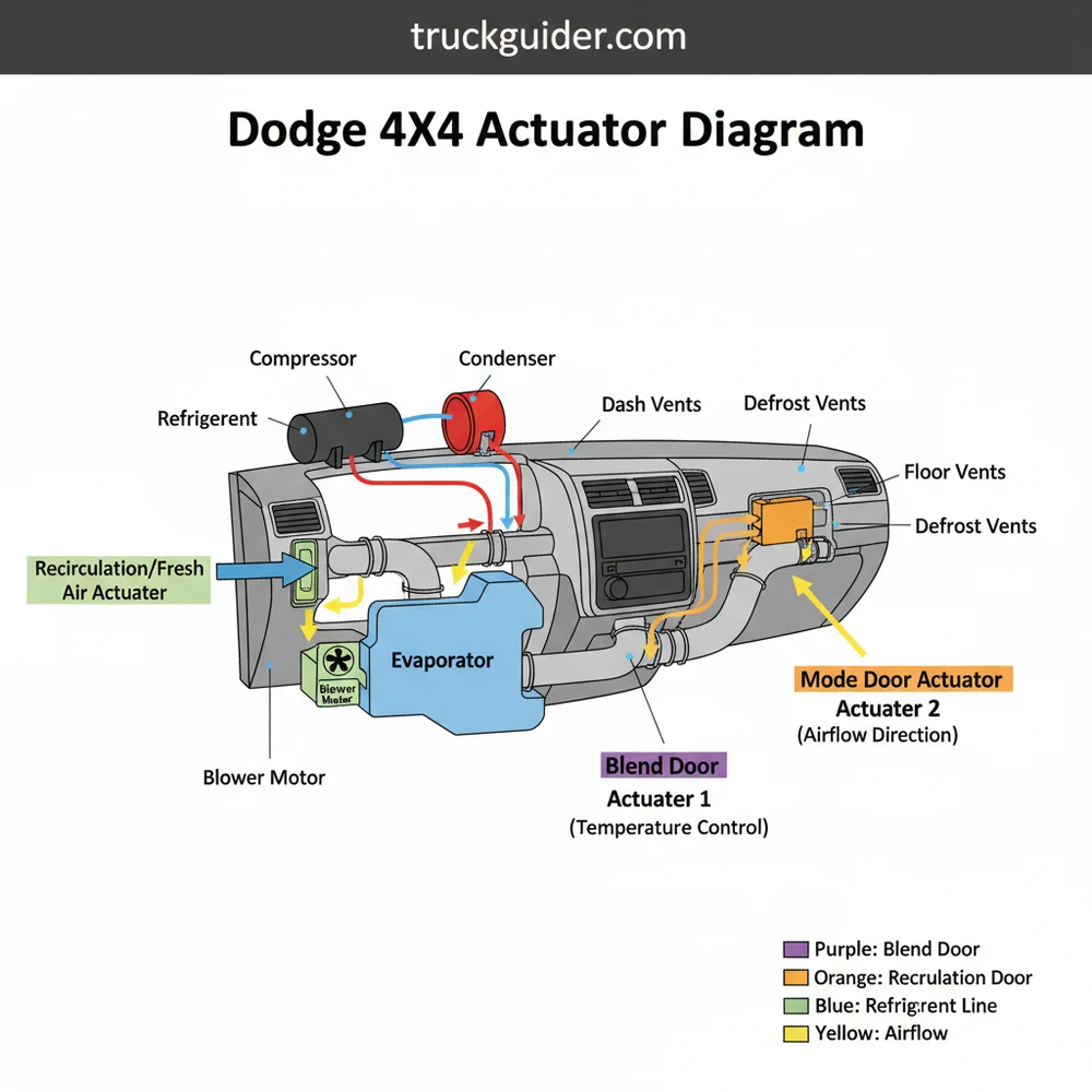
[DIAGRAM_PLACEHOLDER: DODGE HVAC ACTUATOR & REFRIGERANT SYSTEM LAYOUT]
The diagram displays the Compressor (engine bay), Condenser (front of radiator), and Evaporator (inside air handler). Lines indicate the flow of refrigerant. Actuators are shown mounted to the Air Handler unit with wiring harnesses leading to the Climate Control Module.
Understanding the broader HVAC context is essential for using the dodge 4×4 actuator diagram successfully. The refrigerant cycle starts at the compressor, which is driven by the engine belt. The compressor pressurizes the refrigerant, sending it to the condenser at the front of the vehicle to shed heat. From there, the refrigerant travels back toward the cabin to the evaporator. As the blower motor pushes air over the cold evaporator coils, heat is absorbed, and the resulting cold air is managed by the actuators within the air handler. If an actuator fails, the cold air produced by the compressor and evaporator might never reach the cabin, or it might be incorrectly mixed with hot air from the heat exchanger, leading to poor climate performance even if the mechanical cooling components are functioning perfectly.
Before replacing an actuator, check the blower motor and cabin air filter. Low airflow caused by a clogged return duct or a failing blower motor can sometimes mimic the symptoms of a stuck mode door actuator.
Interpreting a dodge 4×4 actuator diagram and performing a repair requires a methodical approach. Follow these steps to navigate the system:
- ✓ Step 1: Identify the Symptom – Determine if the issue is temperature-related (blend door) or direction-related (mode door). This allows you to isolate the specific actuator on the diagram.
- ✓ Step 2: Locate the Component – Use the diagram to find the physical location of the actuator. Most Dodge trucks require the removal of the lower dash panels or the glovebox for access.
- ✓ Step 3: Inspect the Wiring Harness – Refer to the diagram’s wire colors. Check the connector for signs of melting, corrosion, or loose pins. Ensure the ground wire has a solid connection to the chassis.
- ✓ Step 4: Verify Power and Ground – Using a multimeter and the pinout provided in the diagram, confirm that the actuator is receiving 12 volts of power when the ignition is on and that the signal wire fluctuates when you adjust the climate controls.
- ✓ Step 5: Test the Mechanical Linkage – Sometimes the actuator is fine, but the plastic door or “arm” inside the air handler is broken. Remove the actuator and try to move the door manually to ensure it rotates freely.
- ✓ Step 6: Install and Calibrate – After installing a new actuator, many Dodge vehicles require a calibration sequence. This often involves pulling the HVAC fuse for 60 seconds, reinserting it, and turning the key to the “on” position without starting the engine to let the computer sweep the doors to their limit stops.
Safety is paramount when working with these systems. While the actuators themselves are low-voltage, they are located near the evaporator and heat exchanger. The evaporator contains pressurized refrigerant, and the heat exchanger contains scalding hot engine coolant.
Never attempt to disconnect refrigerant lines leading to the evaporator without a professional recovery machine. Refrigerant can cause instant frostbite and is hazardous to the environment.
When troubleshooting based on your dodge 4×4 actuator diagram, look for common failure patterns. One of the most frequent issues is a rhythmic “clicking” or “thumping” sound coming from behind the dashboard. This indicates that the plastic gears inside the actuator have stripped, or the stop-point on the door has broken, causing the motor to jump teeth as it attempts to find its position. Another common sign is “dual-zone” confusion, where one side of the truck blows hot and the other blows cold; this is almost always a failure of one of the two blend door actuators found in higher-trim Dodge models.
The diagram is also helpful when diagnosing vacuum leaks. If your air defaults to the defrost position regardless of the setting, it usually means the system has lost vacuum pressure. By tracing the lines on the dodge 4×4 actuator diagram back to the engine’s vacuum pump or intake manifold, you can find cracked hoses or a faulty check valve that is preventing the actuators from holding a position. If the actuators are working but you still have no cold air, the diagram helps you transition your diagnosis to the compressor and condenser. A compressor that does not engage could be due to a low refrigerant charge, which is detected by the high-pressure and low-pressure switches shown in the electrical portion of the schematic.
Modern Dodge actuators are “smart” devices that communicate via a LIN-bus (Local Interconnect Network). A dodge 4×4 actuator diagram for newer trucks will show a single data wire rather than multiple individual power lines for each door.
To ensure the longevity of your HVAC system and its actuators, follow a few best practices. First, avoid the habit of slamming your climate control dials from one extreme to the other. Rapid changes in command can put unnecessary stress on the plastic gears within the actuator and the doors themselves. Second, keep the return duct and cabin air filter clean. When the blower motor has to work harder to pull air through a restricted filter, it creates a pressure imbalance inside the air handler that can make it more difficult for the actuators to move the doors against the force of the air.
If you find that you need to replace an actuator, always opt for high-quality or OEM components. Many aftermarket actuators use inferior plastic for the internal gears, which may fail again within a year, especially in extreme temperatures where the plastic becomes brittle. Furthermore, during any dash-disassembly process, take the time to inspect the heat exchanger for leaks. A small coolant leak can create a sticky residue inside the air handler that “glues” the doors in place, eventually burning out the motors of your new actuators.
Maintaining the HVAC system in a 4×4 vehicle is about understanding the synergy between the chemical refrigerant cycle and the mechanical air delivery system. The compressor, condenser, and evaporator do the heavy lifting of heat exchange, but without a functioning set of actuators, that comfort never reaches the driver. By utilizing a dodge 4×4 actuator diagram, you gain the clarity needed to navigate the complex wiring and ductwork of your vehicle. Whether you are replacing a clicking blend door or tracing a vacuum leak that has disabled your defrost, the diagram is your roadmap to a successful repair. With the right tools, a bit of patience, and a solid understanding of the HVAC components, you can ensure your Dodge remains a comfortable environment regardless of the weather outside.
In conclusion, the dodge 4×4 actuator diagram is an indispensable tool for any vehicle owner or technician. It bridges the gap between the high-pressure world of refrigerant and the delicate mechanical movements required for cabin climate control. By regularly checking the blower motor, maintaining the integrity of the air handler, and ensuring the return duct is clear, you provide the optimal environment for your actuators to perform. When issues arise, the systematic approach of identifying the symptom, verifying power via the diagram, and performing a calibration will lead you to a professional-grade fix. Keep your diagram handy, understand the LSI components like the heat exchanger and condenser, and you will be well-equipped to handle any HVAC challenge your Dodge truck presents.
Step-by-Step Guide to Understanding the Dodge 4X4 Actuator Diagram: Diagnosis & Fix Guide
Identify the specific actuator causing the malfunction by cycling through vent modes and temperature settings.
Locate the actuator using the diagram, typically by removing the glove box or the panel under the steering column.
Understand how the wiring harness connects to the actuator and check for any visible damage or melted connectors.
Connect the new actuator to the harness before mounting to verify that it rotates when the controls are moved.
Verify that the internal door moves freely by hand before Installing the new motor to prevent premature failure.
Complete the installation by securing the mounting screws and performing a calibration sweep via the HVAC control head.
Frequently Asked Questions
Where is the HVAC actuator located?
On most Dodge 4×4 models, the actuators are located behind the dashboard. The blend door actuator is typically found behind the glove box, while the mode door actuator is positioned near the driver’s side floor duct or behind the center stack near the blower motor housing.
What does a Dodge 4×4 actuator diagram show?
The diagram shows the electrical pinouts, wiring harness colors, and the physical mounting positions of the actuators within the HVAC plenum. It details how the control module signals the motors to divert air over the evaporator or heater core to manage the cabin’s climate effectively.
How many wires does the blend door actuator have?
Most Dodge HVAC actuators utilize a 3-wire or 5-wire connection. A 3-wire setup typically includes power, ground, and a signal wire, while a 5-wire configuration adds feedback potentiometer lines that tell the computer the exact position of the door for precise temperature modulation.
What are the symptoms of a bad actuator?
Common symptoms include a repeating clicking or knocking sound from the dash, air only blowing from specific vents regardless of settings, or inconsistent temperatures. If the compressor and refrigerant levels are fine but air remains warm, a faulty blend door actuator is the likely culprit.
Can I replace the HVAC actuator myself?
Yes, many actuators are accessible by removing the glove box or lower trim panels. However, some mode doors located high in the dash may require significant disassembly. Most DIYers can handle the blend door actuator with basic hand tools and a bit of patience.
What tools do I need for actuator replacement?
You will generally need a 1/4-inch drive ratchet, a set of small sockets (usually 5.5mm, 7mm, or 8mm), and a trim removal tool. A flashlight is also essential for seeing into the tight spaces behind the condenser and heater core housing components.


![Best Aftermarket Rear Bumpers [2026]](https://truckguider.com/wp-content/uploads/2026/03/aftermarket-rear-bumper-featured.webp)